
A distribution transformer on-load capacity and voltage regulation system

A technology for distribution transformers and voltage regulation systems, applied in transformers, variable transformers, transformer/inductor components, etc., can solve problems such as voltage fluctuations, difficult automatic control, and inrush currents, and achieve stable current and voltage fluctuations. The effect of stable waveform and smooth transition process

Active Publication Date: 2018-09-11
JIANGSU ELECTRIC POWER CO +2
View PDF3 Cites 0 Cited by
  • Summary
  • Abstract
  • Description
  • Claims
  • Application Information

AI Technical Summary

Problems solved by technology

However, the invention adopts star-delta conversion for the capacity adjustment wiring, and switching the capacity of the transformer under the condition of uninterrupted power supply will generate inrush current, which is not easy to realize automatic control; at the same time, the voltage on the low-voltage side will also have large fluctuations, which will affect the distribution transformer. The automatic pressure regulation process has a great impact, which is not conducive to the comprehensive control of capacity and pressure regulation

Method used


Image

  • A distribution transformer on-load capacity and voltage regulation system
  • A distribution transformer on-load capacity and voltage regulation system

Examples


Embodiment

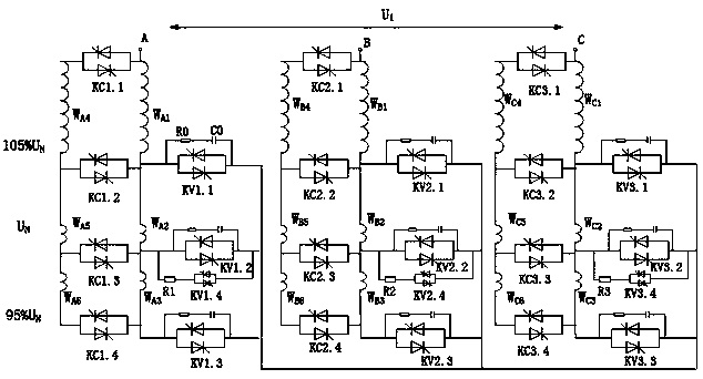
[0013] The on-load capacity and voltage regulation system of the distribution transformer in this embodiment takes a distribution transformer with a voltage regulation range of ±1×5% UN as an example. The distribution transformer includes 3 taps, which are 95%, 100% and 105%, respectively. Such as figure 1 with figure 2 As shown, including: A-phase winding, B-phase winding and C-phase winding installed on the high-voltage side of the distribution transformer, and a-phase winding, B-phase winding and C-phase winding installed on the low-voltage side of the distribution transformer. The three voltage-regulating taps of the A-phase winding are respectively connected in series with the tap-changers KV1.1, KV1.2 and KV1.3 and then connected together. Similarly, the three voltage-regulating taps of the B-phase winding are respectively connected in series with the tap-changer KV2.1 , KV2.2 and KV2.3, the three voltage regulating taps of the C-phase winding are respectively connecte...


PUM


Abstract

The invention relates to an on-load capacitance and voltage regulation system of a power distribution transformer, and belongs to the technical field of power equipment. The system comprises an A-phase winding, a B-phase winding and a C-phase winding of a high-voltage side and an a-phase winding, a b-phase winding and a c-phase winding of a low-voltage side, wherein the A-phase winding, the B-phase winding and the C-phase winding each is provided with a voltage regulation tap, the voltage regulation taps of the A-phase winding, the B-phase winding and the C-phase winding are respectively connected with a tap switch and then are connected together, the A-phase winding, the B-phase winding and the C-phase winding each comprises two high-voltage coils, initial ends and tail ends of the two high-voltage coils and the positions of the voltage regulation taps are connected by a first capacitance regulation switch, the a-phase winding, the b-phase winding and the c-phase winding each comprises two low-voltage coils, and initial ends and tail ends of the two low-voltage coils are connected by a second capacitance regulation switch. In the on-load capacitance and voltage regulation system of the power distribution transformer, provided by the invention, thyristors which are reversely connected in parallel are taken as the capacitance and voltage regulation switches of the power distribution transformer, and the capacitance and the voltage of the power distribution transformer can be automatically and rapidly adjusted; and during the switching process, the current and the voltage are stable in fluctuation, and influence on sensitive users in a power grid and a power distribution network cannot be generated.

Description

technical field [0001] The invention relates to an on-load capacity and voltage regulation system of a distribution transformer, which belongs to the technical field of electric power equipment. Background technique [0002] In my country's vast rural and suburban distribution networks, the load seasonality is obvious, the peak-to-valley difference is large, and the power quality is low. Therefore, it is very necessary to design a distribution transformer with automatic on-load capacity regulation and voltage regulation. At present, although domestic distribution transformers with load capacity and voltage regulation are put into operation, most of the distribution transformers only have the function of voltage regulation or capacity regulation. At the same time, most of the on-load voltage regulation or capacity regulation distribution transformers in my country currently use mechanical switches. Mechanical switches have the disadvantages of slow switching speed, inaccura...

Claims


Application Information

Patent Timeline
Patent Type & Authority Patents(China)
IPC IPC(8): H01F29/04H01F27/28H01F27/40H02P13/00
CPCH01F27/2823H01F27/40H01F29/04H02P13/00
Inventor 马宏忠顾苏雯许洪华王华芳王春宁徐晗
Owner JIANGSU ELECTRIC POWER CO
Learn More