Eureka AIR delivers breakthrough ideas for toughest innovation challenges, trusted by R&D personnel around the world.

Corner nailing machine

A nailing machine and frame technology, applied in the direction of nailing tools, staple nailing tools, manufacturing tools, etc., can solve the problems of increased equipment cost, short service life, easy to generate noise, etc., to reduce friction, Effect of improving service life and reducing noise

Active Publication Date: 2017-02-08
江门沙龙实业有限公司
View PDF6 Cites 4 Cited by
  • Summary
  • Abstract
  • Description
  • Claims
  • Application Information

AI Technical Summary

Problems solved by technology

The nailing process of some small or simple-structured products is generally relatively simple, and only needs to be nailed once or twice. The processing of this product does not require frequent movement of the nailing mechanism, and only needs to be used to position the workpiece on the workbench. The positioning mechanism can be movably set on the workbench to meet the requirements, which can greatly reduce the equipment cost, but the existing equipment generally uses an ordinary pushing mechanism to push or pull the positioning mechanism, which has a large friction force and is prone to noise. And the service life is short, it needs to be replaced frequently, which increases the cost of equipment

Method used


Image

  • Corner nailing machine
  • Corner nailing machine
  • Corner nailing machine

Examples


Embodiment Construction

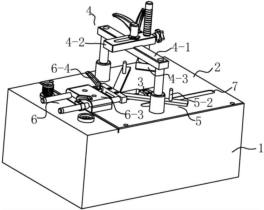
[0019] refer to figure 1 , a kind of nailing machine of the present invention comprises frame 1, and described frame 1 is provided with workbench 2, and the lower surface of described workbench 2 is fixedly installed with nailing mechanism 3 and is used for driving nailing mechanism 3 up and down The first cylinder of the action, the workbench 2 is provided with a through hole for nailing corresponding to the nailing mechanism 3, and the top of the workbench 2 is provided with a pressing mechanism 4 corresponding to the nailing mechanism 3, and the pressing mechanism 4 is connected with a The second cylinder of the tightening mechanism 4 moving up and down, the upper surface of the workbench 2 is provided with a positioning mechanism 5, the positioning mechanism 5 includes a number of positioning bars that are set corresponding to the shape of the workpiece, and the positioning bars are fixedly connected with a pushing mechanism 6, and the positioning The bar can freely slide ...


PUM


Abstract

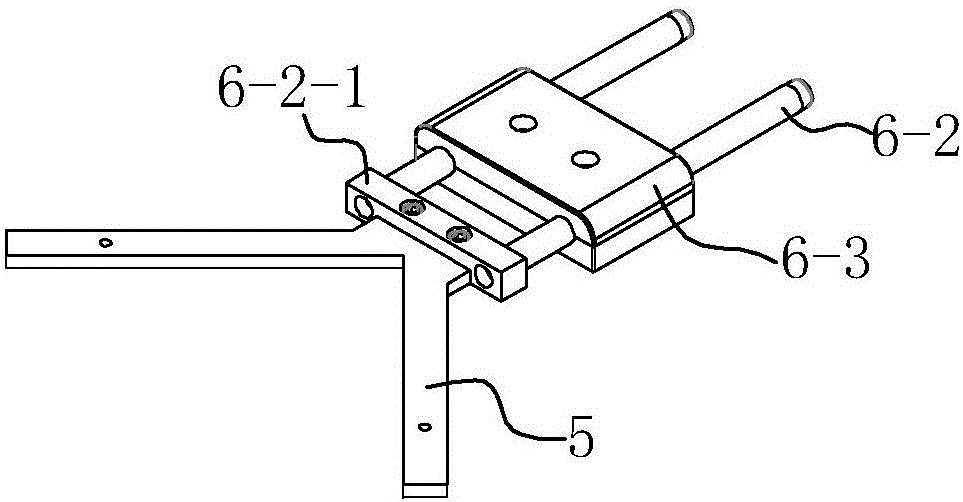
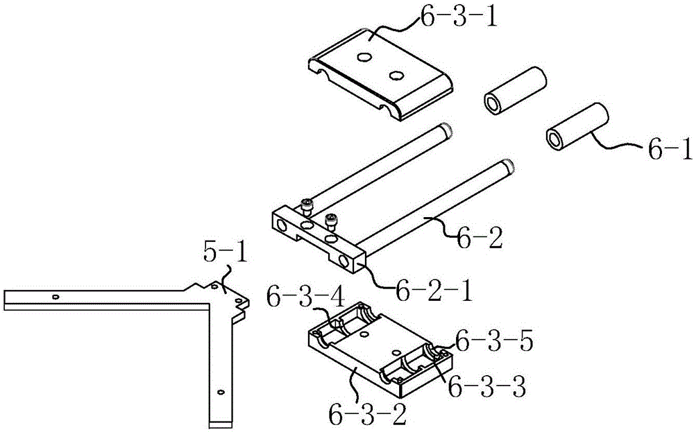
The invention discloses a corner nailing machine. A positioning mechanism is arranged at the upper surface of a worktable; the positioning mechanism comprises a plurality of positioning bars which are arranged corresponding to the shape of a work piece; the positioning bars are fixedly connected with a push mechanism and are capable of freely sliding along the upper surface of the worktable; the push mechanism comprises a sliding bearing, a push rod and a bearing seat, wherein the push rod is mounted in the sliding bearing; the bearing seat is used for mounting the sliding bearing; the push rod is capable of freely sliding along the sliding bearing; the bearing seat is fixedly arranged at the upper surface of the worktable; a limiting block is also arranged on the push rod. By moving the position of the work piece, the corner nailing machine disclosed by the invention is capable of realizing processing of a small product or a simply structured product and greatly lowering the cost of equipment; moreover, the push mechanism adopts the sliding bearing; by arranging relational structures of a bearing bush and an oil filling hole, the push friction force can be reduced, noises are reduced, and the service life of the push mechanism is prolonged.

Description

technical field [0001] The invention relates to a nailing machine. Background technique [0002] The nailing machine is mainly used for fixing the edges of wooden frames such as photo frames and picture frames. Generally, the corners of the two photo frames are cut to 45 degrees, and after joining, they are stitched together with nailing machines. The nailing process of some small or simple-structured products is generally relatively simple, and only needs to be nailed once or twice. The processing of this product does not require frequent movement of the nailing mechanism, and only needs to be used to position the workpiece on the workbench. The positioning mechanism can be movably set on the workbench to meet the requirements, which can greatly reduce the equipment cost, but the existing equipment generally uses an ordinary pushing mechanism to push or pull the positioning mechanism, which has a large friction force and is prone to noise. And the service life is short, ne...

Claims


Application Information

Patent Timeline
IPC IPC(8): B27F7/02
CPCB27F7/02
Inventor 敬智勇
Owner 江门沙龙实业有限公司
Why Eureka
Eureka Blog
Learn More