Umbrella-shaped valve and combined-floating-body type hydrant

An umbrella valve and water supply plug technology, which is applied in the field of agricultural irrigation, can solve the problems of large opening force of the water plug, poor water flow, water leakage, etc., and achieve the effect of enhancing the anti-theft ability and smooth water flow

Inactive Publication Date: 2017-02-08
宋庆波
View PDF3 Cites 3 Cited by
  • Summary
  • Abstract
  • Description
  • Claims
  • Application Information

AI Technical Summary

Problems solved by technology

[0003] 1. The floating body valve is placed on the slideway in the lower bolt body. During the lifting and landing process, due to the impact of water flow, the floating body valve may get stuck in some cases, resulting in lax automatic closing and water leakage.
[0004] 2. The floating body valve is an integral structure with a large buoyancy force. In the upstream of the irrigation project, when the water pressure in the pipe is too high, the opening force of the water supply plug is very large, resulting in damage to the upper plug body and the lower plug body drive nut. question
[0005] 3. During operation, the water flow flows around the floating body valve. The water flow is not smooth due to the water blocking of the slideway and chute around the floating body valve. At the same time, the top surface of the floating body is relatively large. The position forms a vacuum negative pressure, causing vibration during operation
[0006] 4. The anti-theft cover is equipped with air intake and exhaust holes, resulting in poor air intake and exhaust

Method used


Image

  • Umbrella-shaped valve and combined-floating-body type hydrant
  • Umbrella-shaped valve and combined-floating-body type hydrant
  • Umbrella-shaped valve and combined-floating-body type hydrant

Examples


Embodiment Construction

[0046] as the picture shows:

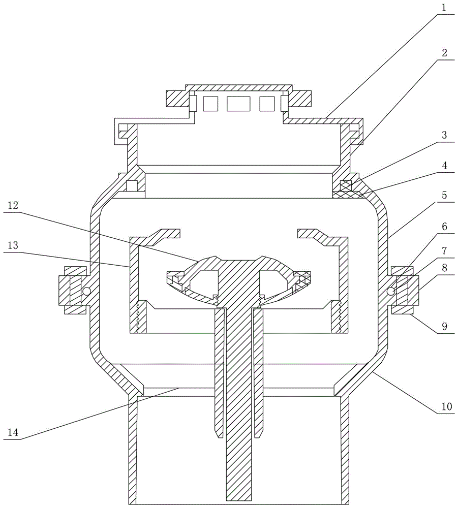
[0047] The invention provides an umbrella valve, comprising:

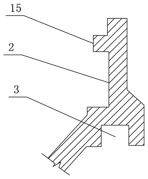
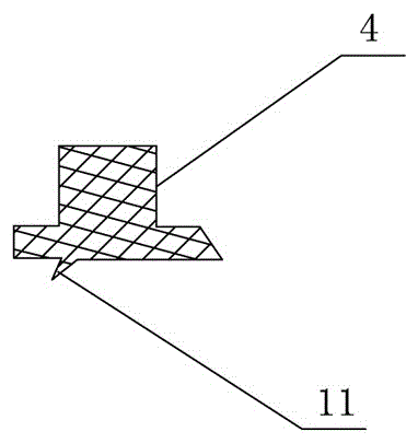
[0048] Described umbrella valve is mainly made up of umbrella valve plate 12 and guide rod 25, and umbrella valve plate 12 top surface central position is provided with concave push valve seat 26, and umbrella valve plate 12 outer edge is provided with water-stop rubber ring 23 and The reserved hole 27 and the reserved groove of the water-stop rubber ring; the top surface of the water-stop rubber ring 23 is provided with a convex ring water-stop line 11 with an inclined angle, the umbrella-shaped valve plate 12 is a hollow structure with a trapezoidal section, and the bottom of the hollow area is a bottom seal The cover 24 and the bottom cover 24 are circular arc-shaped structures, the center of which is a cylindrical internal thread structure, and a guide rod 25 is arranged in the cylindrical internal thread structure, and the thread on the top of the guide rod 25 and the cylindrical...


PUM


Abstract

An umbrella-shaped valve is mainly composed of a valve plate and a guide rod. A concave push valve seat is arranged at the center of the top face of the valve plate. The outer edge of the valve plate is provided with a water stop rubber ring, a water stop rubber ring reserved hole and a reserved groove. The top face of the water stop rubber ring is provided with a convex ring water stop line with an inclination angle. The valve plate is of a trapezoidal-cross-section hollow structure. A bottom seal cover is arranged at the bottom of a hollow area and is of a circular-arc-shaped structure. The center of the bottom seal cover is of a cylindrical internally-threaded structure. The guide rod is arranged in the cylindrical internally-threaded structure. Threads on the upper portion of the guide rod are connected with the cylindrical internally-threaded structure in a glue joint manner.

Description

technical field [0001] The invention belongs to the technical field of agricultural irrigation, and in particular relates to a water supply cock. Background technique [0002] The patentee of the prior art closest to the present invention is Song Jian, whose patent number is 201410034701.7. This patent also has the following problems: [0003] 1. The floating body valve is placed on the slideway in the lower bolt body. During the lifting and lowering process, due to the impact of water flow, the floating body valve may get stuck in some cases, resulting in lax automatic closing and water leakage. [0004] 2. The floating body valve is an integral structure with a large buoyancy force. In the upstream of the irrigation project, when the water pressure in the pipe is too high, the opening force of the water supply plug is very large, resulting in damage to the upper plug body and the lower plug body drive nut. question. [0005] 3. During operation, the water flow flows arou...

Claims


Application Information

Patent Timeline
Patent Type & Authority Applications(China)
IPC IPC(8): F16K1/36F16K1/46F16K31/20F16K27/02F16K27/12F16K35/06F16K24/00A01G25/00
CPCF16K1/36A01G25/00F16K1/46F16K24/00F16K27/02F16K27/12F16K31/20F16K35/06
Inventor 宋庆波
Owner 宋庆波
Why Eureka
Try Eureka