
Shielding structure of voltage transformer

A technology of voltage transformer and shielding structure, applied in the direction of inductors, transformers, circuits, etc., can solve problems such as correct judgment of interference product quality, carbon accumulation and dust accumulation, and pollution of voltage transformers.

Active Publication Date: 2017-02-08
天津市百利纽泰克电气科技有限公司
View PDF6 Cites 0 Cited by
  • Summary
  • Abstract
  • Description
  • Claims
  • Application Information

AI Technical Summary

Problems solved by technology

[0004] At present, for 10kV voltage transformers with fuses, due to structural reasons, when conducting insulation tests and partial discharge tests, there is uneven field strength between the fuse and the resin, resulting in strong or weak but more obvious discharge phenomena. The partial discharge of the product is relatively large, which will affect the correct judgment of the main insulation defect of the transformer itself, and will interfere with the correct judgment of the product quality or cause the product to be rejected by mistake
Long-term discharge during operation will easily cause pollution, carbon and dust accumulation in the voltage transformer, which will cause ground discharge or breakdown accidents, and even cause more serious phase-to-phase short-circuit accidents, which will bring greater hidden dangers to the safe operation of the system

Method used


Image

  • Shielding structure of voltage transformer
  • Shielding structure of voltage transformer
  • Shielding structure of voltage transformer

Examples


Embodiment Construction

[0016] In order to further understand the invention content, characteristics and effects of the present invention, the following examples are given, and detailed descriptions are as follows in conjunction with the accompanying drawings:

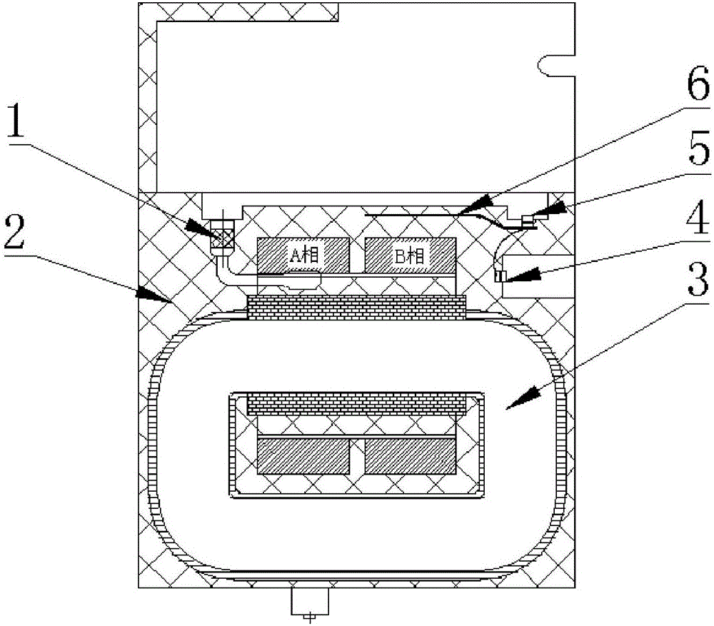
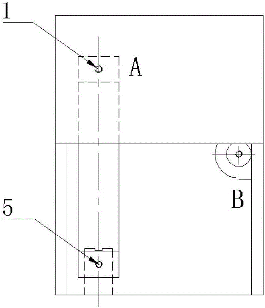
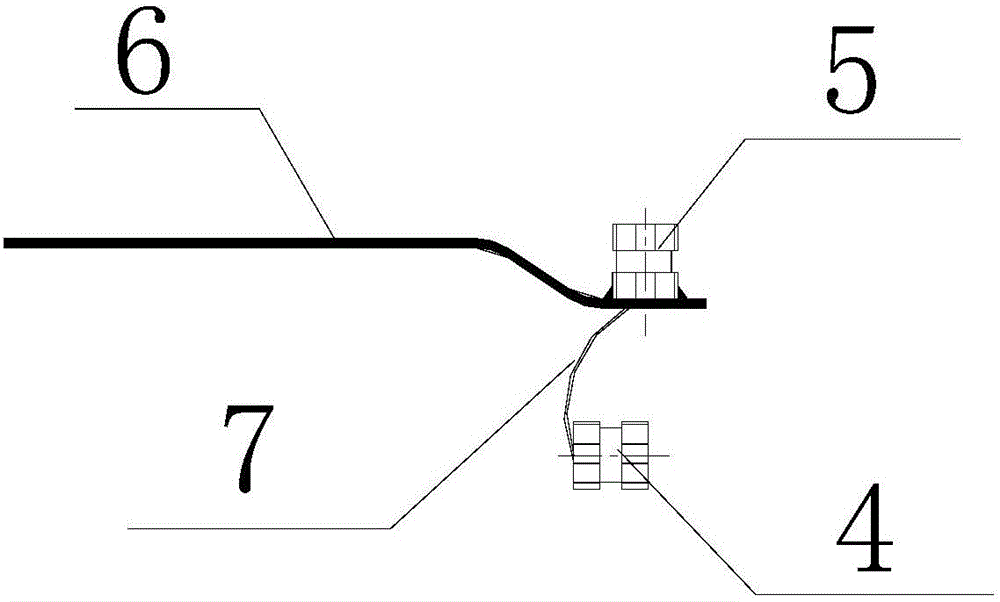
[0017] see Figure 1 to Figure 4 , a shielding structure of a voltage transformer, the voltage transformer is a 10kV voltage transformer with a fuse, the voltage transformer includes a transformer body 3, and epoxy resin 2 is poured on the transformer body 3; The A-phase terminal and the B-phase terminal of the voltage transformer are buried in the epoxy resin 2; the A-phase terminal is electrically connected to the A-phase primary terminal 1 through a wire; the shielding structure includes: a first mounting insert 4, The second installation insert 5 and the shielding net assembly 6; the A-phase primary terminal 1 is connected to the second installation insert 5 through a fuse; the first installation insert 4 is connected to the second instal...


PUM


Abstract

The invention discloses a shielding structure of a voltage transformer. The voltage transformer is a 10kV voltage transformer with a fuse; the voltage transformer comprises a voltage transformer body; epoxy resin is cast on the transformer body; a phase A terminal and a phase B terminal of the voltage transformer are buried in the epoxy resin; the phase A terminal is electrically connected with the phase A primary terminal through a conducting wire. The shielding structure is characterized by comprising a first installing embedding element, a second installing embedding element and a shielding net assembly; the phase A primary terminal is connected with the second installing embedding element through a fuse; the first installing embedding element is connected with the second installing embedding element through an equipotential connection wire; the shielding net assembly is positioned between the phase A primary terminal and the second installing embedding element; in addition, the shielding net assembly is embedded in the epoxy resin. Through the shielding structure of the voltage transformer, no potential difference exist in the epoxy resin; the discharging generating mechanism is eliminated; further, the external discharging phenomenon due to structure reasons can be avoided; the electric performance defects inside the product can be better judged.

Description

technical field [0001] The invention relates to the technical field of voltage transformers, in particular to a shielding structure of a voltage transformer. Background technique [0002] As we all know, the potential transformer (Potential transformer referred to as PT, Voltage transformer also referred to as VT) is very similar to the transformer, they are used to transform the voltage on the line. However, the purpose of transforming the voltage of the transformer is to transmit electric energy, so the capacity is very large, and it is generally calculated in kilovolt-ampere or megavolt-ampere; The power supply of the protection device is used to measure the voltage, power and electric energy of the line, or to protect the valuable equipment, motor and transformer in the line when the line fails. Therefore, the capacity of the voltage transformer is very small, generally only a few volts, Dozens of VA, hundreds of VA. However, in some special places, thousands of VA vol...

Claims


Application Information

Patent Timeline
IPC IPC(8): H01F27/36H01F38/26
CPCH01F27/36H01F38/26
Inventor 孙世元孙树英王丽娟蔚浩王洋
Owner 天津市百利纽泰克电气科技有限公司
Learn More