
Method for observing three-dimensional discharge morphology of soil around grounding device

A grounding device and soil technology, which is applied in the high-voltage field, can solve the problems of lack of soil discharge characteristics, large differences between ground rod discharge and the actual situation, and hinder the flow path of soil current, so as to improve reliability and safety and reduce discharge.

Pending Publication Date: 2021-08-27
CHINA ELECTRIC POWER RES INST +3
View PDF0 Cites 0 Cited by
  • Summary
  • Abstract
  • Description
  • Claims
  • Application Information

AI Technical Summary

Problems solved by technology

[0004] 1. Mainly study the discharge characteristics of soil under power frequency, lack of research on soil discharge characteristics under lightning impact transient;
[0005] 2. The form of the discharge gap is mainly tip-plate, tip-tip, ball-ball, but in practice, the grounding body is usually connected and combined by a rod-shaped grounding device, so it lacks the discharge characteristics of the wire-rod gap
[0006] 3. Although the shape of the soil discharge around the grounding body can be captured by embedding X-ray film near the grounding body in the ground, because the X-ray film and the grounding rod are arranged in parallel and close to each other, the X-ray film hinders the current flow path in the soil. Causes the discharge around the ground rod to be quite different from the actual
[0007] 4. Chongqing University observes soil discharge by taking pictures with a space X-ray camera. However, due to the very fast attenuation of X-rays, this method can only capture the strong discharge of the main discharge channel, and cannot observe the discharge branches before and after the formation of the main channel.

Method used


Image

  • Method for observing three-dimensional discharge morphology of soil around grounding device
  • Method for observing three-dimensional discharge morphology of soil around grounding device
  • Method for observing three-dimensional discharge morphology of soil around grounding device

Examples


Embodiment Construction

[0029] Exemplary embodiments of the present invention will now be described with reference to the drawings; however, the present invention may be embodied in many different forms and are not limited to the embodiments described herein, which are provided for the purpose of exhaustively and completely disclosing the present invention. invention and fully convey the scope of the invention to those skilled in the art. The terms used in the exemplary embodiments shown in the drawings do not limit the present invention. In the figures, the same units / elements are given the same reference numerals.

[0030] Unless otherwise specified, the terms (including scientific and technical terms) used herein have the commonly understood meanings to those skilled in the art. In addition, it can be understood that terms defined by commonly used dictionaries should be understood to have consistent meanings in the context of their related fields, and should not be understood as idealized or over...


PUM


Abstract

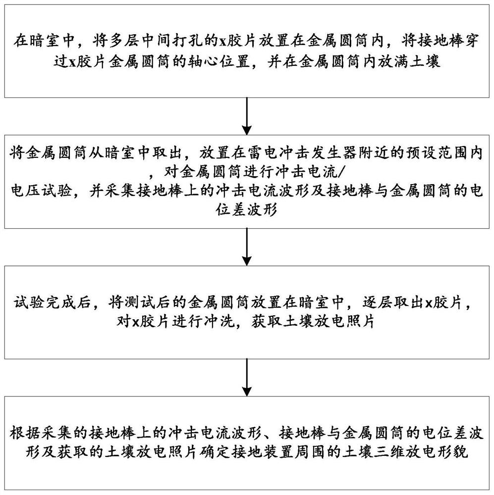
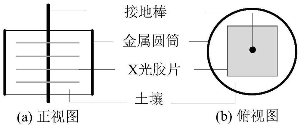
The invention discloses a method for observing the three-dimensional discharge morphology of soil around a grounding device, which belongs to the technical field of high voltage. The method comprises the following steps of in a darkroom, placing a plurality of layers of x films with holes in the middle in a metal cylinder, penetrating a grounding rod through the axis position of the x film metal cylinder, and filling the metal cylinder with soil, taking out the metal cylinder from the darkroom, placing the metal cylinder in a preset range near a lightning impulse generator, and performing an impulse current / voltage test on the metal cylinder, acquiring a soil discharge picture, and determining the three-dimensional discharge morphology of the soil around the grounding device according to the acquired impact current waveform on the grounding rod, the potential difference waveform of the grounding rod and the metal cylinder and the acquired soil discharge picture. The morphology of soil discharge can be observed in all directions.

Description

technical field [0001] The invention relates to the field of high-voltage technology, and more specifically, to a method for observing the three-dimensional discharge morphology of soil around a grounding device. Background technique [0002] Our country suffers frequent lightning strikes every year, causing great harm. Good grounding is a key measure for lightning protection. Lightning protection equipment such as lightning rods, lightning wires and lightning arresters must be equipped with corresponding grounding devices to guide the lightning current into the earth for discharge. Because the lightning current is very large, it will generate a high potential gradient in the soil when it flows into the ground through the grounding device, and when it exceeds the withstand field strength of the soil, the discharge phenomenon will occur in the soil. The discharge of the soil will greatly affect the lightning impulse characteristics of the grounding device, resulting in a no...

Claims


Application Information

Patent Timeline
Patent Type & Authority Applications(China)
IPC IPC(8): G01R31/12
CPCG01R31/1218G01R31/1263
Inventor 张波罗东辉谭波何金良宋伟曹艳川曹永兴
Owner CHINA ELECTRIC POWER RES INST
Learn More