Fabrication of capacitive micromachined ultrasonic transducers by local oxidation

a capacitive micromachined and ultrasonic transducer technology, applied in the direction of mechanical vibration separation, electrical apparatus, basic electric elements, etc., can solve the problems of difficult to control the thickness of the membrane, the difficulty of adjusting the gap height or thickness, and the stress of the membrane, etc., to achieve low parasitic capacitance, high breakdown voltage, and cost-effective

Active Publication Date: 2010-06-29
THE BOARD OF TRUSTEES OF THE LELAND STANFORD JUNIOR UNIV
View PDF14 Cites 77 Cited by
  • Summary
  • Abstract
  • Description
  • Claims
  • Application Information

AI Technical Summary

Benefits of technology

[0013]The present invention has numerous advantages over existing techniques of fabricating CMUTs by providing independent and precise gap thickness and post thickness control to allow for CMUTs with low parasitic capacitance and high breakdown voltage. The fabrication method of the present invention provides for cost-effective and highly reproducible devices. In addition, the fabrication method presented herein ensures smooth surface roughness without requiring any chemical-mechanical polishing.

Problems solved by technology

This technique has numerous intrinsic drawbacks, including: stiction problems that may prevent the release of the membrane; stress in the membrane that is very sensitive to deposition conditions; difficulties in controlling the membrane thickness due to successive deposition and etching steps; and difficulties to control the gap height or thickness due to the unwanted non-uniform nitride deposition in the cavity during sealing.
However, since the gap height is determined through an etching process, gap height control is difficult.
In addition, the minimum gap height is limited by the thickness of the original oxide layer, requiring design compromise in terms of breakdown voltage and parasitic capacitance.

Method used


Image

  • Fabrication of capacitive micromachined ultrasonic transducers by local oxidation
  • Fabrication of capacitive micromachined ultrasonic transducers by local oxidation
  • Fabrication of capacitive micromachined ultrasonic transducers by local oxidation

Examples


examples

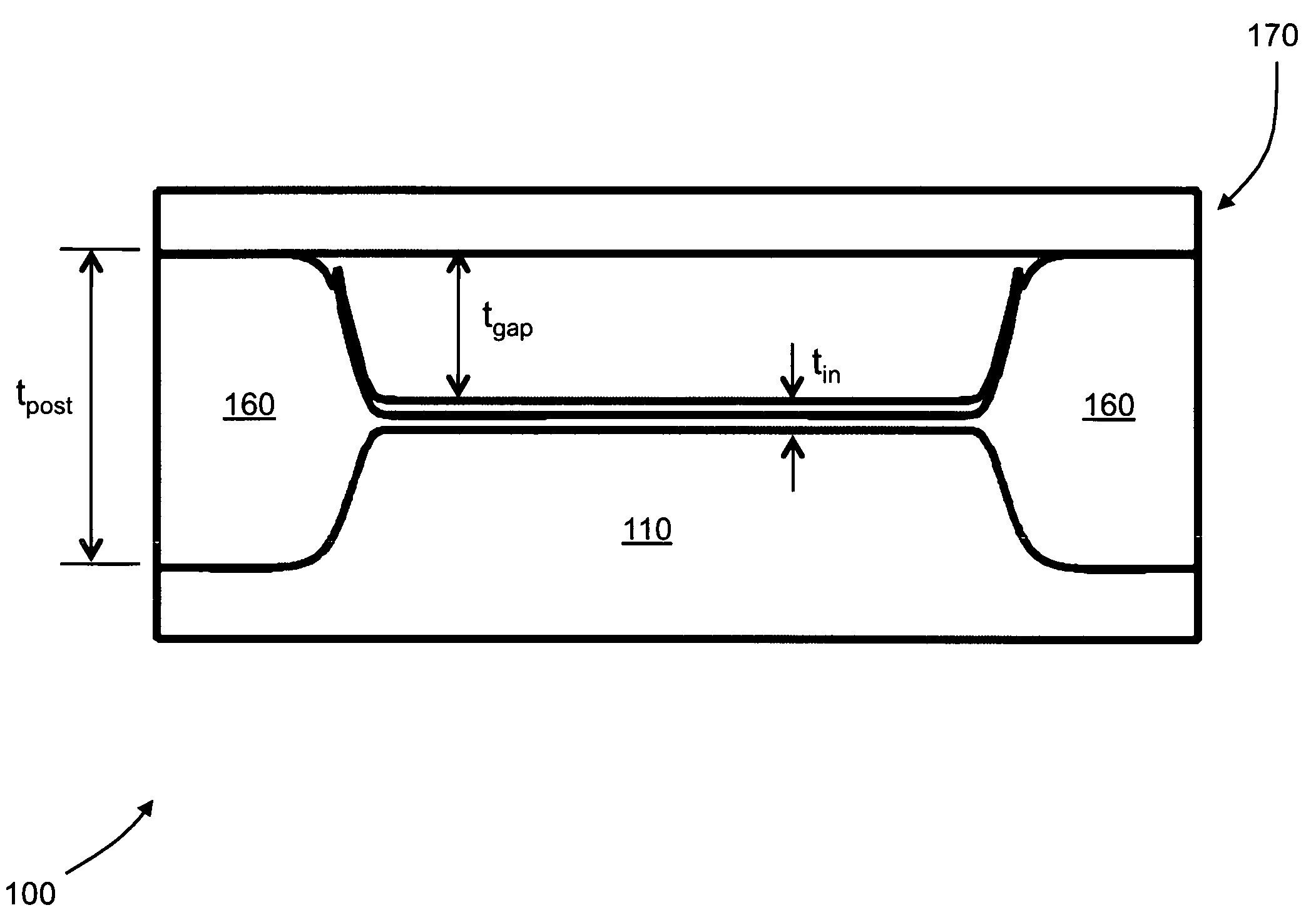
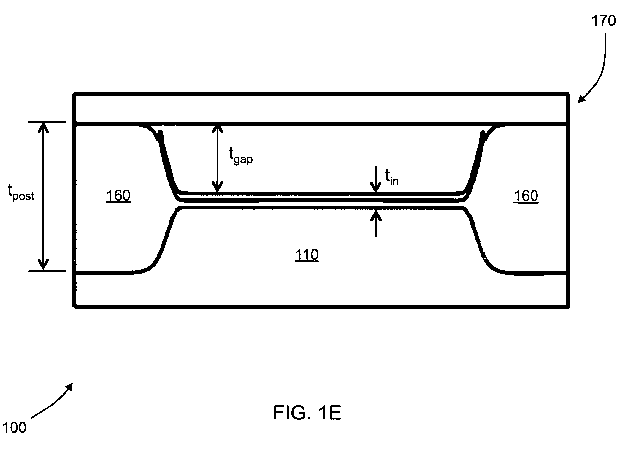
[0060]CMUTs for HIFU therapy require a thick vacuum gap for high output pressure and a high breakdown voltage. An example HIFU CMUT, similar to the CMUT 700 of FIG. 7E, requires tpost=2 μm, tin=0.2 μm, and tgap=0.3 μm. Based on these required thicknesses, a step height of tstep=0.62 μm is desired. The maximum allowed second oxidation thickness t2=5 μm is determined based on this desired step height tstep and the size of the CMUT to be fabricated. The first oxidation thickness t1=1.7 μm is calculated based on the determined t2 and the step height tstep. The calculated t1 and determined t2 give a 6:1 BOE over-etch time of 3.9 minutes. The substrate step is fabricated following the process of FIG. 14 and the HIFU CMUT is fabricated from the process of FIG. 7.

[0061]CMUTs for imaging require a thin vacuum gap for better sensitivity and thick oxide posts for low parasitic capacitance. In addition, a flat substrate step is required for better performance and larger step heights generally r...


PUM


Abstract

The current invention provides methods of fabricating a capacitive micromachined ultrasonic transducer (CMUT) that includes oxidizing a substrate to form an oxide layer on a surface of the substrate having an oxidation-enabling material, depositing and patterning an oxidation-blocking layer to form a post region and a cavity region on the substrate surface and remove the oxidation-blocking layer and oxide layer at the post region. The invention further includes thermally oxidizing the substrate to grow one or more oxide posts from the post region, where the post defines the vertical critical dimension of the device, and bonding a membrane layer onto the post to form a membrane of the device. A maximum allowed second oxidation thickness t2 can be determined, that is partially based on a desired step height and a device size, and a first oxidation thickness t1 can be determined that is partially based on the determined thickness t2.

Description

CROSS-REFERENCE TO RELATED APPLICATIONS[0001]This application claims priority from U.S. Provisional Patent Application 60 / 999,657 filed Oct. 18, 2007, which is incorporated herein by reference.FEDERALLY-SPONSORED RESEARCH OR DEVELOPMENT[0002]This invention was made with Government support under contract N66001-06-1-2030 awarded by the Space and Naval Warfare Systems Center. The Government has certain rights in this invention.FIELD OF THE INVENTION[0003]The invention relates generally to capacitive micromachined ultrasonic transducers (CMUTs). More particularly, the present invention relates to fabrication of CMUTs by local oxidation.BACKGROUND[0004]Capacitive micromachined ultrasonic transducers (CMUTs) are gaining increasing popularity in the fields of medical and underwater imaging. In addition, CMUT technology has recently been used for applications such as high intensity focused ultrasound (HIFU) therapy and resonating chemical sensors. The basic structure of a CMUT includes a t...

Claims


Application Information

Patent Timeline
Patent Type & Authority Patents(United States)
IPC IPC(8): H01L21/00
CPCB06B1/0292
Inventor PARK, KWAN KYUKUPNIK, MARIOKHURI-YAKUB, BUTRUS T.
Owner THE BOARD OF TRUSTEES OF THE LELAND STANFORD JUNIOR UNIV
Why Eureka
Try Eureka