Surgical medical device
A technology of medical equipment and surgery, which is applied in the field of medical equipment, and can solve the problems that surgical medical equipment does not have automatic reset function and cannot be automatically reset.
- Summary
- Abstract
- Description
- Claims
- Application Information
AI Technical Summary
Problems solved by technology
Method used
Image
Examples
Embodiment
[0046] Embodiment: a kind of surgical operation medical instrument.
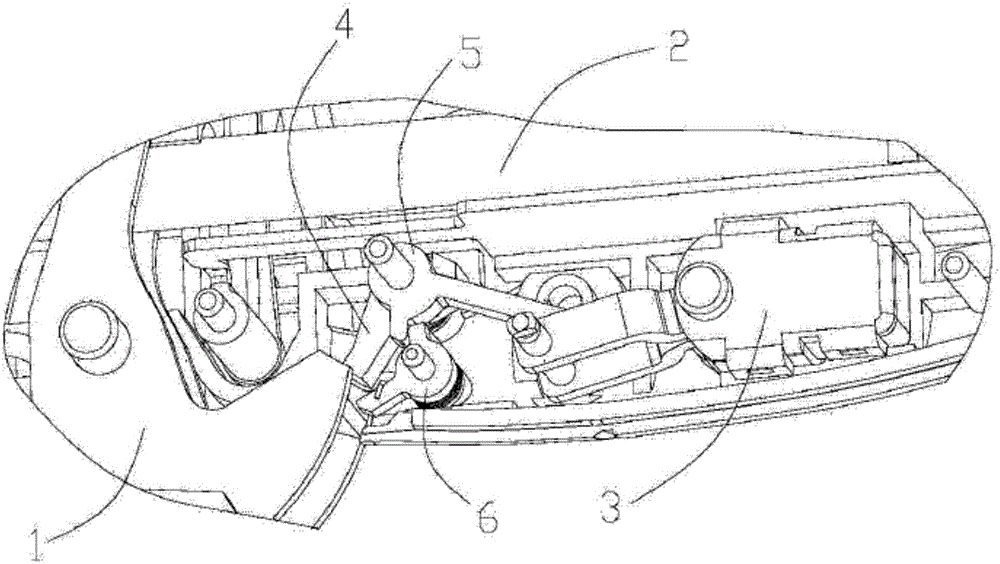
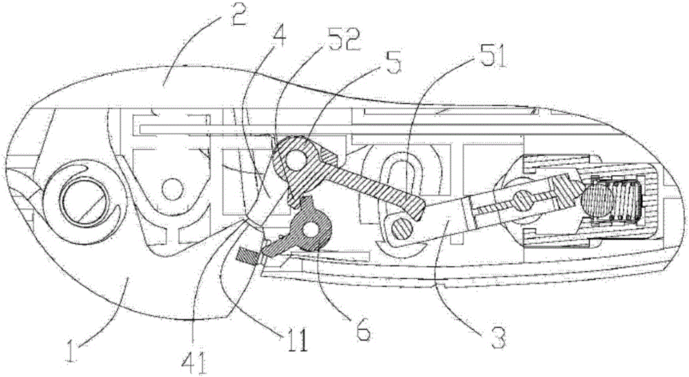
[0047] This embodiment provides an optional figure 1 The tubular stapler shown, the partial enlarged view of detail A of the above tubular stapler is shown in Figure 1-A as shown, Figure 1-A The schematic diagram of the Figure 1-B As shown, including firing handle 1, shell 2 and safety switch device 3, also includes such as diagram 2-1 Inner insurance block 4 shown, as image 3 Shown main living bar 5 and as Figure 4 Shown secondary live bar 6. Another three-dimensional schematic diagram of the above-mentioned inner insurance block 4 is shown in Figure 2-2, as Figure 1-A and Figure 1-B As shown, the above-mentioned inner safety block 4 is in the initial state of the above-mentioned tubular stapler against the above-mentioned firing handle 1 to prevent firing, and the above-mentioned inner safety block 4 is passed as Figure 5 The shown first torsion spring 7 is rotatably connected with the abo...
Embodiment 2
[0065] This embodiment provides an optional tubular stapler, the safety switch device 3 of the tubular stapler includes: a base 3.1; a lever 3.2, the lever 3.2 is connected to the base 3.1 through a connecting part 3.21 , the above-mentioned driving rod 3.2 rotates around the above-mentioned connecting member 3.21, the first end 3.24 of the above-mentioned driving rod is located inside the above-mentioned base 3.1, and the second end 3.25 of the above-mentioned driving rod is located outside the above-mentioned base 3.1; The component is located inside the above-mentioned base 3.1, the above-mentioned first end 3.24 of the above-mentioned driving rod 3.2 is in contact with the above-mentioned limiting member, when the above-mentioned driving rod 3.2 rotates to the first limiting position with the above-mentioned connecting member 3.21 as the axis, the above-mentioned The limiting component and the first part 3.11 of the above-mentioned base 3.1 form a clamping connection with t...
Embodiment 3
[0067] On the basis of Embodiment 2, the above-mentioned limiting component includes: a limiting movement part. The interior is located at the first position. When the above-mentioned lever 3.2 rotates from the first limit position to the second limit position with the above-mentioned connecting part 3.21 as the axis, the limit movement part first moves from the first position to the second limit position. The opposite side of the first end portion 3.24 moves to the second position, and then moves from the second position to the first position.
PUM
 Abstract
Description
Claims
Application Information
 - R&D
- Intellectual Property
- Life Sciences
- Materials
- Tech Scout
- Unparalleled Data Quality
- Higher Quality Content
- 60% Fewer Hallucinations
Browse by: Latest US Patents, China's latest patents, Technical Efficacy Thesaurus, Application Domain, Technology Topic, Popular Technical Reports.
© 2025 PatSnap. All rights reserved.Legal|Privacy policy|Modern Slavery Act Transparency Statement|Sitemap|About US| Contact US: help@patsnap.com


