Glue spraying device and determination method of border track

A technology of spraying glue and frame, which is applied to the device and coating of the surface coating liquid, which can solve the problems of reduced execution efficiency of the whole machine, unstable glue spraying, and affecting the shooting accuracy of the CCD vision system, so as to avoid debugging Steps, simplify the operation process, improve the effect of shooting accuracy

Active Publication Date: 2017-02-15
GUANGDONG OPPO MOBILE TELECOMM CORP LTD
View PDF10 Cites 23 Cited by
  • Summary
  • Abstract
  • Description
  • Claims
  • Application Information

AI Technical Summary

Problems solved by technology

[0005] Since the CCD vision system of the above-mentioned glue spraying machine is fixedly connected with the piezoelectric spray valve, the high-frequency vibration generated when the spray valve is working will affect the shooting accuracy of the CCD vision system, resulting in unstable glue spraying
In addition, this structure enables the visual positioning and glue spraying operations t

Method used


Image

  • Glue spraying device and determination method of border track
  • Glue spraying device and determination method of border track
  • Glue spraying device and determination method of border track

Examples


Embodiment 1

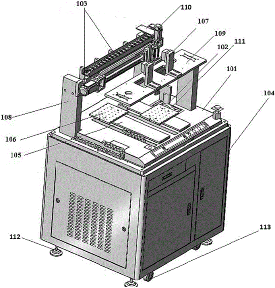
[0024] figure 1 It is a perspective view of a glue spraying device provided in Embodiment 1 of the present invention. Such as figure 1 As shown, the glue spraying device includes: a workbench 101 , a controller (not shown), a glue spraying mechanism 102 , a motion actuator, a camera module (not shown) and a feeding module 105 .

[0025] The workbench 101 has a camera mounting frame 109 , a glue spraying mechanism mounting frame 108 and the loading module 105 . Wherein, the workbench 101 is arranged on the top of the control cabinet 104 . The control cabinet 104 is fixed on the lowermost end of the glue spraying device, and the bottom of the control cabinet 104 is provided with a support 112, so that the distance between the control cabinet 104 and the ground is set at a height, which is convenient for controlling the heat dissipation of the electronic equipment in the cabinet 104, and avoiding Moisture on the ground can affect the normal operation of electronic equipment. ...

Embodiment 2

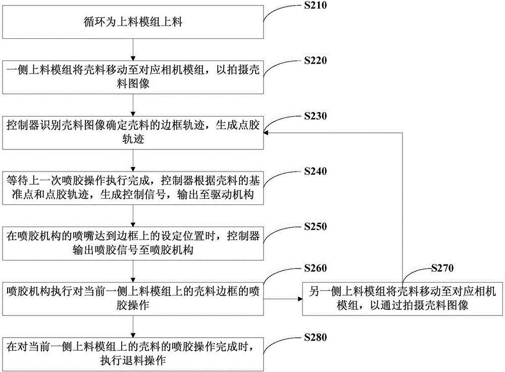
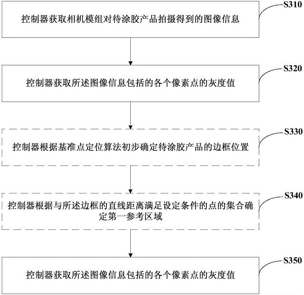
[0067] image 3 It is a flow chart of a method for determining the frame trajectory provided by Embodiment 2 of the present invention. This embodiment is applicable to the case of determining the frame of a narrow frame product. This method can be executed by the glue spraying device in the above embodiment. Specifically Including the following steps:

[0068] Step 310, the controller obtains the image information captured by the camera module on the product to be glued.

[0069] Wherein, the image information includes a plurality of sub-image information about the product to be glued, and the complete image information of the product to be glued is obtained after splicing the sub-image information.

[0070] Exemplarily, the controller acquires the first sub-image and the second sub-image obtained by taking two shots of the product to be glued by the camera module, and splicing the first sub-image and the second sub-image to obtain the corresponding image of the product to be...

Embodiment 3

[0080] Figure 4 It is a flow chart of a method for determining a frame trajectory provided by Embodiment 3 of the present invention. Such as Figure 4 As shown, the method specifically includes the following steps:

[0081] Step 410: Obtain a pre-drawn glue road map corresponding to the product to be glued, and generate a first frame track according to the glue road map.

[0082] The glue road for the glue spraying operation of the product to be glued can be drawn in advance according to the design drawing, using a drawing tool, and saved as a glue road diagram corresponding to the glue sprayed product. When it needs to be used, import the glue road map of the corresponding product to be glued into the glue spraying device, and the first frame track of the product to be glued to be sprayed can be automatically generated in the glue spraying device. Exemplarily, according to the design drawing of the shell material to be glued, the glue road map corresponding to the shell m...


PUM


Abstract

The invention discloses a glue spraying device and a determination method of a border track. The glue spraying device is characterized in that a camera mounting rack, a glue spraying mechanism mounting rack and feeding modules are arranged on a workbench of the device; camera modules are arranged on the camera mounting rack, and are used for shooting a to-be-glued product on the feeding modules to acquire the image information; a controller is used for acquiring the image information, determining the border track and a datum point of the to-be-glued product, generating a dispensing track according to the border track, generating a control signal according to the dispensing track and the datum point, outputting the control signal to a motion performing mechanism, and outputting a glue spraying signal to a glue spraying mechanism when a nozzle of the glue spraying mechanism reaches a set position on a border; the motion performing mechanism is used for driving the glue spraying mechanism and the feeding modules to perform corresponding position adjustment action of the control signal; and the glue spraying mechanism is arranged on the glue spraying mechanism mounting rack, and is used for opening a glue spraying valve according to the glue spraying signal and performing the glue spraying operation. According to the glue spraying device, the problem that the precision cannot meet the requirement when a conventional glue spraying device sprays glue to a narrow border is solved.

Description

technical field [0001] Embodiments of the present invention relate to a device for coating liquid or other fluids on a surface, and in particular to a glue spraying device and a method for determining a frame track. Background technique [0002] As a mobile terminal integrating communication, entertainment, office and other functions, smart phones have become one of the indispensable electronic devices in people's daily life. [0003] The screen is getting bigger and bigger, and the frame is getting narrower and narrower, which has become the development trend of smart phones. However, due to the limitation of frame manufacturing accuracy, for the middle shells of different models from different manufacturers, there will be deformation in the frame area or there will be tolerance problems with the drawings. As a result, the glue spraying operation on the frame of the smart phone cannot meet the required accuracy, and the problem of glue overflow is prone to occur. [0004]...

Claims


Application Information

Patent Timeline
IPC IPC(8): B05C5/00B05C11/10B05C13/00B05C11/00
CPCB05C5/00B05C11/00B05C11/1002B05C11/1015B05C13/00
Inventor 魏巍
Owner GUANGDONG OPPO MOBILE TELECOMM CORP LTD
Why Eureka
Try Eureka