Track type water removal method for rubber assembly of tire

A crawler and rubber technology, which is applied in the field of rubber tire production, can solve the problems of small contact area, low water absorption efficiency, and inability to absorb water cleanly, so as to prolong the service life and save energy

Active Publication Date: 2017-02-15
山东新大陆橡胶科技有限公司
View PDF7 Cites 2 Cited by
  • Summary
  • Abstract
  • Description
  • Claims
  • Application Information

AI Technical Summary

Problems solved by technology

Compared with patent ZL201120555189.2, the patent ZL201020169996.6 increases the contact area between the sponge and the rubber component, but it is still a line contact, and the contact area is still small; there is also no relative displacement between the contact surface of the sponge and the rubber component, and the water absorption The efficiency is not high; the water in the sponge roller is not squeezed out, and after a long time of operation, the water on the upper surface of rubber components such as treads and sidewalls cannot be completely absorbed

Method used


Image

  • Track type water removal method for rubber assembly of tire
  • Track type water removal method for rubber assembly of tire
  • Track type water removal method for rubber assembly of tire

Examples


Embodiment 1

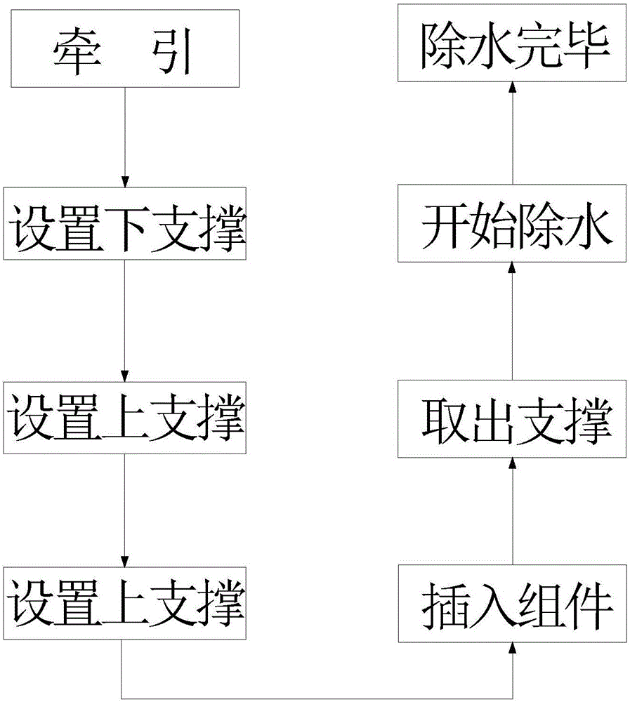
[0038] The technical process of the crawler-type dewatering method for the tire rubber assembly that the present embodiment relates to comprises the following steps:

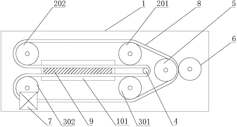
[0039] (1) Traction: pull the tire rubber assembly 9 from other conveying devices in front of the crawler water removal device to the channel opening of the material channel 101 of the crawler water removal device;

[0040] (2) Setting the lower support: Insert a thin steel sheet with a width equal to the width of the crawler-shaped sponge 8, a length greater than the distance between the lower supporting roller 301 and the inner direction-changing roller 4, and a thickness less than 2 mm into the middle gap formed by the crawler-shaped sponge 8 inside;

[0041] (3) Set the side support: insert two prying rollers into the middle gap formed by the track-shaped sponge 8, and place them on the thin steel sheet respectively, and the distance between the two prying rollers is greater than the width of the tire rubber a...

Embodiment 2

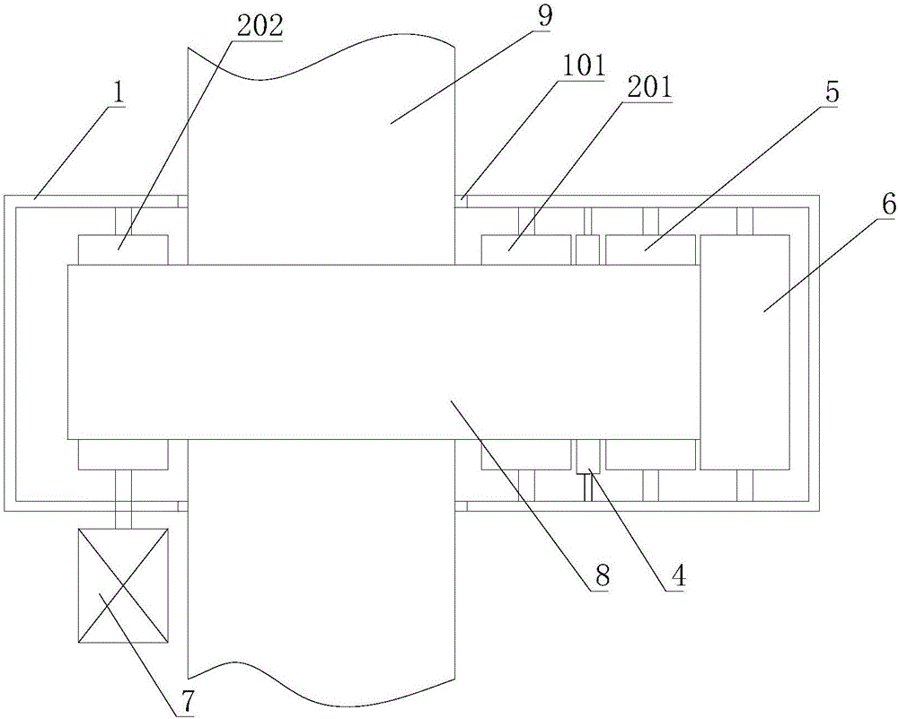
[0054] The crawler-type water removal method for tire rubber components involved in this embodiment is implemented by a crawler-type water removal device, and its main composition structure is the same as that of Embodiment 1, the difference lies in the gap between the upper support roller 201 and the upper tail support roller 202 An upper middle support roller 203 is provided; a lower middle support roller 303 is provided between the lower head support roller 301 and the lower tail support roller 302 .

Embodiment 3

[0056] The crawler-type water removal method for tire rubber components involved in this embodiment is implemented by a crawler-type water removal device. Its main composition structure is the same as that of Embodiment 1, except that it also includes a water receiving tank 10, which is located outside the transformer. To the bottom of the gap between the roller 5 and the squeeze roller 6; the water receiving tank 10 is shaped as a strip-shaped long groove, the long side of the water receiving tank 10 is parallel to the axis of the water squeezing roller 6, and the length of the long side of the water receiving tank 10 is greater than that of the track-shaped sponge The width of the water receiving tank 10 is connected with a drain pipe 11 at the bottom of the water tank 10; discharge.


PUM


Abstract

The invention relates to a track type water removal method for a rubber assembly of a tire. The method comprises steps as follows: (1) traction is performed; (2) a lower support is arranged; (3) a side support is arranged; (4) an upper support is arranged; (5) the assembly is inserted; (6) the supports are taken out; (7) water removal is started; (8) water removal is completed. With the method, the rubber assembly can pass through a track type sponge smoothly on the premise that the track type sponge is protected against damage; a track type water removal device removes water on surfaces of the rubber assembly efficiently and cleanly in the manner that the sponge rubs against the upper surface and the lower surface of the rubber assembly of the tire, water stains on the upper surface and the lower surface of the rubber assembly of the tire can be dried by one sponge, energy is saved, and the device has the characteristics of environment-friendliness; and the service life of the track type sponge can be prolonged by the aid of cord fabric layer.

Description

[0001] Technical field: [0002] The invention belongs to the technical field of rubber tire production, and in particular relates to a crawler-type dewatering method for tire rubber components, which efficiently and cleanly wipes off the moisture on the surface of the rubber components by friction between the sponge and the upper and lower surfaces of the tire rubber components . [0003] Background technique: [0004] In the production process of existing tires, due to the high temperature of rubber components such as sidewalls and treads after being extruded from the machine head, cooling is required. Most tire manufacturers use water cooling to cool down, and rubber components such as sidewalls and treads pass through After spraying and cooling, water droplets and water stains will adhere to the upper and lower surfaces. Due to process requirements, there must be no moisture on the surface of the various components when they are laminated and assembled, otherwise it will a...

Claims


Application Information

Patent Timeline
Patent Type & Authority Applications(China)
IPC IPC(8): B08B1/02B29C47/08B29D30/16B29D30/30
CPCB08B1/006B08B1/02B29C48/274B29D30/16B29D30/30B29D2030/1664B29D2030/3064
Inventor 王金山刘奇王成杰
Owner 山东新大陆橡胶科技有限公司
Why Eureka
Try Eureka