Rotatable separation rolling mill and separation method thereof

A technology of rotating separation and rolling mill, applied in the direction of metal rolling stand, metal rolling mill stand, metal rolling, etc., can solve the problems of long time consumption, unfavorable continuous production of production line, high labor intensity, etc.

Pending Publication Date: 2017-02-15
DALIAN FIELD HEAVY MACHINERY MFG CO LTD
View PDF11 Cites 0 Cited by
  • Summary
  • Abstract
  • Description
  • Claims
  • Application Information

AI Technical Summary

Problems solved by technology

In the rolling mill in the prior art, its rolls are generally fixed on the frame by various locking parts such as bolts. When the rolls need to be replaced, each locking part needs to be manually disassembled, and then a suitable roll is

Method used


Image

  • Rotatable separation rolling mill and separation method thereof
  • Rotatable separation rolling mill and separation method thereof
  • Rotatable separation rolling mill and separation method thereof

Examples


Embodiment Construction

[0033] In order to enable those skilled in the art to better understand the technical solutions of the present invention, the present invention will be further described in detail below in conjunction with the accompanying drawings and specific embodiments.

[0034] Words such as "first" and "second" mentioned herein are only used to distinguish two or more parts or structures with the same or similar structure, and do not represent any special limitation on the order.

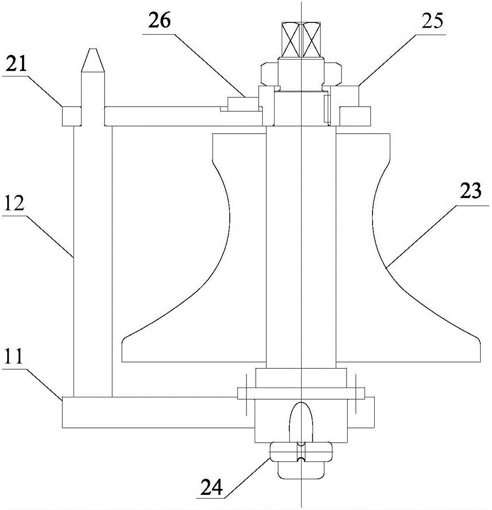
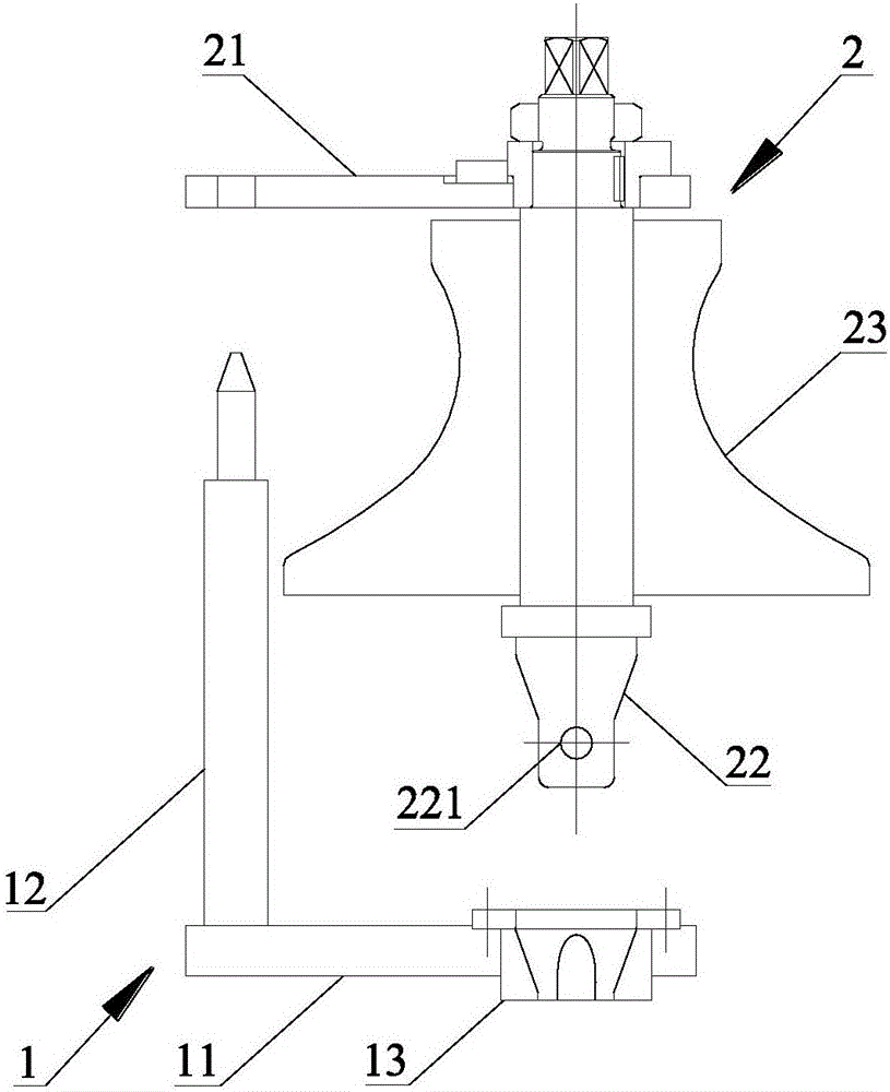
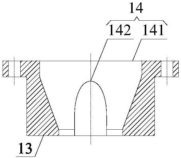
[0035] Please refer to Figure 1-7 , figure 1 It is a structural schematic diagram of a specific embodiment of a rotatably separated rolling mill provided by the present invention, figure 2 for figure 1 Schematic diagram of the structure of the fixed frame and the roll frame, image 3 for figure 2 Schematic diagram of the middle flange, Figure 4 for image 3 bottom view of Figure 5 for figure 2 Schematic diagram of the structure of the first support plate, Image 6 for Figure 5 sectional view o...


PUM


Abstract

The invention discloses a rotatable separation rolling mill and a separation method thereof. The rotatable separation rolling mill comprises a fixing rack and a roller rack, the roller rack comprises a shaft and a roller, the shaft is sleeved with the roller, an insertion hole is formed in the fixing rack, a limiting shaft extending in the radial direction is arranged at the second end of the shaft, and the second end of the shaft can be inserted into the insertion hole; and when the shaft is inserted into the insertion hole, the shaft is rotated, the limiting shaft can abut against the fixing rack, and therefore axial displacement of the roller rack is limited. When the rotatable separation rolling mill is installed and replaced, overall installation and rotation positioning can be carried out on the roller rack, and the installation and replacement process are rapider.

Description

technical field [0001] The invention relates to the technical field of rolling mills, in particular to a rotatable and separable rolling mill and a separation method thereof. Background technique [0002] In the production process of plates and pipes, in order to obtain different types of products, it is necessary to replace different types of rolls. In the rolling mill in the prior art, its rolls are generally fixed on the frame by various locking parts such as bolts. When the rolls need to be replaced, each locking part needs to be manually disassembled, and then a suitable roll is replaced. Reinstalling the above-mentioned locking parts, the entire replacement process basically relies on manpower, which is labor-intensive and time-consuming, which is not conducive to the continuous production of the production line. [0003] Therefore, how to provide a rolling mill that can quickly replace rolls is still a technical problem to be solved urgently by those skilled in the a...

Claims


Application Information

Patent Timeline
IPC IPC(8): B21B31/12
CPCB21B31/12
Inventor 高国武
Owner DALIAN FIELD HEAVY MACHINERY MFG CO LTD
Why Eureka
Try Eureka