
Circular shaft workpiece locking device

A technology for locking devices and workpieces, applied in workpiece clamping devices, manufacturing tools, etc., can solve problems such as high cost, inconvenient operation, complex structure, etc., and achieve the effect of convenient operation, simple structure, compact and reasonable

Inactive Publication Date: 2017-02-15
WUXI CHUANGHENG MACHINERY
View PDF6 Cites 5 Cited by
  • Summary
  • Abstract
  • Description
  • Claims
  • Application Information

AI Technical Summary

Problems solved by technology

But the existing locking device has complex structure, inconvenient operation and high cost

Method used


Image

  • Circular shaft workpiece locking device
  • Circular shaft workpiece locking device
  • Circular shaft workpiece locking device

Examples


Embodiment Construction

[0010] The present invention will be further described below in conjunction with specific drawings and embodiments.

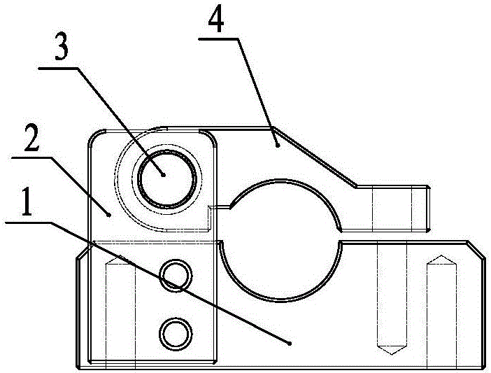
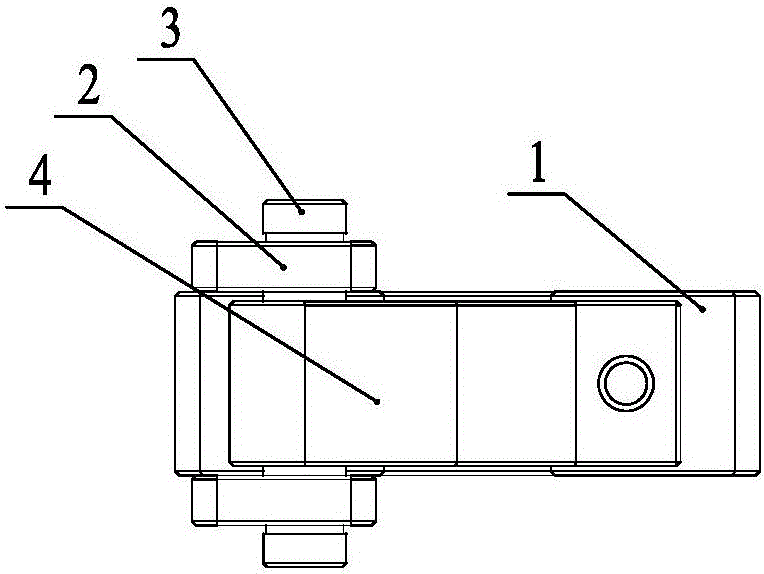
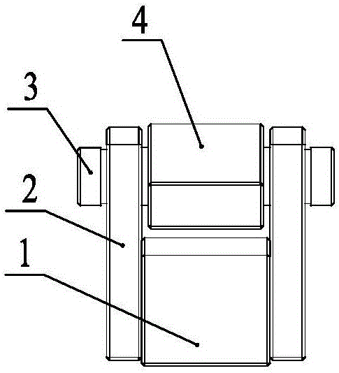
[0011] As shown in the figure: the round shaft workpiece locking device in the embodiment is mainly composed of a lower base 1, a side plate 2, a rotating shaft 3 and an upper chuck 4, and two side plates 2 are installed on both sides of the rear of the lower base 1 , in the illustrated embodiment, the side plate 2 is fixedly installed on the lower base 1 by bolts, and the side plate 2 is detachable for replacement or position adjustment.

[0012] Such as Figure 1~Figure 3 As shown, the rear part of the upper chuck 4 is arranged between the two side plates 2 and is hinged with the two side plates 2 through the rotating shaft 3; the middle top of the lower base 1 and the middle bottom of the upper chuck 4 are respectively set There are corresponding semicircular clamping grooves, the front end of the lower base 1 and the front end of the upper chuck 4 are resp...


PUM


Abstract

The invention relates to a circular shaft workpiece locking device. The circular shaft workpiece locking device is characterized by comprising a lower base, side plates, a rotating shaft and an upper grip, wherein the two side plates are mounted on two sides of the rear part of the lower base; the rear part of the upper grip is arranged between the two side plates and hinged to the two side plates through the rotating shaft; corresponding semi-circular clamping grooves are formed in the middle top of the lower base and the middle bottom of the upper grip; corresponding bolt mounting holes are formed in the front ends of the lower base and the upper grip; and fastening bolts are mounted in the bolt mounting holes. The circular shaft workpiece locking device is simple, compact and reasonable in structure, can realize effective locking of circular shaft workpieces and is convenient to operate and low in manufacturing cost.

Description

technical field [0001] The invention relates to a locking device, in particular to a circular shaft workpiece locking device, which belongs to the technical field of mechanical design. Background technique [0002] In the textile industry and winding industry, a large number of rotating shaft structures are required. In order to ensure safe production, the locking of the rotating shaft is particularly important. However, the existing locking device has complex structure, inconvenient operation and high cost. Contents of the invention [0003] The purpose of the present invention is to overcome the shortcomings in the prior art and provide a circular shaft workpiece locking device. The utility model has the advantages of simple structure, compactness and reasonableness, can effectively lock the circular shaft workpiece, is convenient to operate and has low manufacturing cost. [0004] According to the technical solution provided by the present invention: a circular shaft ...

Claims


Application Information

Patent Timeline
IPC IPC(8): B25B11/00
CPCB25B11/00
Inventor 邹斌
Owner WUXI CHUANGHENG MACHINERY
Learn More