Clamping device based on connecting rod transmission mechanism

A technology of connecting rod transmission and clamper, which is applied in the mechanical field, can solve problems such as clamping failure and reduced clamping precision, and achieve the effect of preventing clamping failure and improving clamping precision

Inactive Publication Date: 2017-02-15
周末
View PDF6 Cites 5 Cited by
  • Summary
  • Abstract
  • Description
  • Claims
  • Application Information

AI Technical Summary

Problems solved by technology

[0003] During the clamping process of the ring-shaped workpiece in the prior art, because the clamping head frequently clamps the workpiece blank for a long time, it is easy to cause clamping failure, resulting in a decrease in clamping accuracy

Method used


Image

  • Clamping device based on connecting rod transmission mechanism

Examples


Embodiment Construction

[0012] In order to make the object, technical solution and advantages of the present invention more clear, the present invention will be further described in detail below in conjunction with the accompanying drawings and embodiments. It should be understood that the specific embodiments described here are only used to explain the present invention, not to limit the present invention.

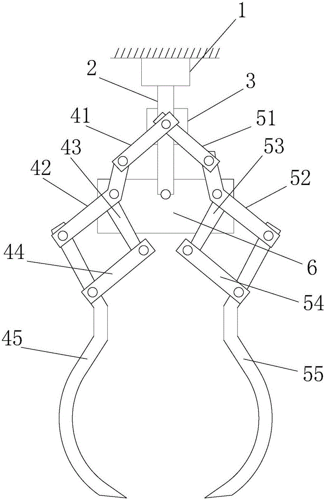
[0013] Such as figure 1 As shown, the clamper based on the link transmission mechanism includes a driver 1, a driving rod 2 located inside the driver 1, a fixing seat 3 is installed on the driving rod 2, and a fixing seat 3 is installed on the fixing seat 3 A connecting rod A41 and a connecting rod B51 are installed on the top, a folding rod A42 is movably installed at one end of the connecting rod A41, a folding rod B52 is movably installed at one end of the connecting rod B51, and a folding rod B52 is installed on the folding rod A42. Adjusting rod A43, adjusting rod B53 is installed on the f...


PUM


Abstract

The invention discloses a clamping device based on a connecting rod transmission mechanism. The clamping device based on the connecting rod transmission mechanism comprises a driver and a driving rod located in the driver, wherein a fixing seat is installed on the driving rod and provided with a connecting rod A and a connecting rod B; a folding rod A is movably installed at one end of the connecting rod A; a folding rod B is movably installed at one end of the connecting rod B; an adjustment rod A is installed on the folding rod A; an adjustment rod B is installed on the folding rod B; a supporting rod A is movably installed at one end of the adjustment rod A; a supporting rod B is movably installed at one end of the adjustment rod B; one end of the driving rod is installed on a fixing block; the folding rod A and the supporting rod A are provided with a clamping head A; and the folding rod B and the supporting rod B are provided with a clamping head B. When the clamping device based on the connecting rod transmission mechanism is used, the driver drives the driving rod to move, the driving rod drives the connecting rod transmission mechanism to move, and the connecting rod transmission mechanism drives the clamping head A and the clamping head B to clamp an annular workpiece.

Description

technical field [0001] The invention relates to the field of mechanical technology, in particular to a clamper based on a link transmission mechanism. Background technique [0002] A clamping mechanism generally refers to a mechanism that clamps or fixes objects such as tools, workpieces, and materials. In mechanical processing, the clamping mechanism refers to the mechanism that fixes the workpiece on the equipment and maintains an accurate processing position. Such as chuck, vise, etc. In the welding industry, the clamping mechanism is a set of mechanisms used to clamp the workpiece in the butt welding machine, and the butt welding process is performed by using this set of clamping mechanisms. [0003] During the clamping process of the ring-shaped workpiece in the prior art, because the clamping head frequently clamps the workpiece blank for a long time, it is easy to cause clamping failure, resulting in a decrease in clamping accuracy. Contents of the invention [0...

Claims


Application Information

Patent Timeline
Patent Type & Authority Applications(China)
IPC IPC(8): B25J9/10B25J15/02
CPCB25J9/106B25J15/022
Inventor 周末
Owner 周末
Why Eureka
Try Eureka