Diaphragm punching device

A diaphragm and punch technology, applied in the field of diaphragm punching device, to achieve the effect of stable work and reasonable structure

Active Publication Date: 2017-02-15
TECHNIMARK PRECISION CASTING SUZHOU CO LTD
View PDF8 Cites 5 Cited by
  • Summary
  • Abstract
  • Description
  • Claims
  • Application Information

AI Technical Summary

Problems solved by technology

[0002] Some products need to assemble the diaphragm, and the diaphragm needs to be punched and pressed into the product, but the existing equipment cannot realize the diaphragm punching and pressing into the product in one step

Method used


Image

  • Diaphragm punching device

Examples


Embodiment Construction

[0022] The specific implementation manners of the present invention will be further described below in conjunction with the drawings and examples. The following examples are only used to illustrate the technical solution of the present invention more clearly, but not to limit the protection scope of the present invention.

[0023] The technical scheme of concrete implementation of the present invention is:

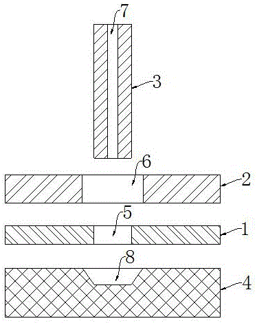
[0024] Such as figure 1 Shown, a kind of diaphragm die-cutting device comprises:

[0025] Flat laying template 1 for tiling the diaphragm,

[0026] A flat pressing plate 2 arranged above the template 1 for pressing the diaphragm,

[0027] The vertical punch 3 arranged above the pressing plate 2,

[0028] a mold 4 arranged under the formwork 1 for placing products to be installed,

[0029] And a driving device for driving the vertical lift of the punch 3;

[0030] The template 1 is provided with a through hole 5 for punching vertically through the punch 3 and cooperat...


PUM


Abstract

The invention discloses a diaphragm punching device. The diaphragm punching device comprises a horizontally-arranged die plate, a horizontally-arranged pressing plate, a vertically-arranged puncher pin, a die and a driving device, wherein the horizontally-arranged die plate is used for flatly spreading a diaphragm; the horizontally-arranged pressing plate is arranged over the die plate and used for pressing the diaphragm; the vertically-arranged puncher pin is arranged above the pressing plate; the die is arranged under the die plate and used for placing a to-be-installed product; and the driving device is used for driving the puncher pin to go up and down perpendicularly. The die plate is provided with a vertical punching through hole which allows the puncher pin to penetrate through and is matched with the puncher pin so that the diaphragm can be punched. The pressing plate is provided with a vertical through hole for allowing the puncher pin to penetrate through vertically. The puncher pin is provided with a center through hole coaxial with the puncher pin. A top end opening of the center through hole is connected with a first negative pressure generation device through a first negative pressure pipeline. The die is provided with a groove for accommodating the product. The groove is located under the puncher pin. The bottom surface of the groove is connected with a second negative pressure generation device through a second negative pressure pipeline. The diaphragm punching device can punch the diaphragm and then press the diaphragm into the product and is reasonable in structure and stable in work.

Description

technical field [0001] The invention relates to a film punching device. Background technique [0002] Some products need to assemble the diaphragm, which needs to be punched and pressed into the product, but the existing equipment cannot realize the diaphragm punching and pressing into the product in one step. Contents of the invention [0003] The purpose of the present invention is to provide a membrane punching device, which can press the membrane into a product after punching, and has a reasonable structure and stable operation. [0004] In order to achieve the above object, the technical solution of the present invention is to design a membrane punching device, comprising: [0005] Laying template for tiling diaphragms, [0006] A flat platen above the formwork for pressing the diaphragm, [0007] The vertical punch set above the platen, [0008] A mold for placing the product to be installed under the formwork, [0009] And the driving device that drives the ver...

Claims


Application Information

Patent Timeline
Patent Type & Authority Applications(China)
IPC IPC(8): B26F1/44B26D7/02B26D7/01
CPCB26D7/015B26D7/018B26D7/025B26F1/44B26F2001/4427
Inventor 孙烈冰
Owner TECHNIMARK PRECISION CASTING SUZHOU CO LTD
Why Eureka
Try Eureka