Stirrer for realizing desulfurization by using mechanical stirring

A mechanical stirring and agitator technology, which is applied in the field of agitators, can solve the problems such as the decline in the service life of the agitator, and achieve the effect of alleviating the short service life, delaying the damage process, and improving economic direct sales

Active Publication Date: 2017-02-15
武汉钢铁有限公司
View PDF7 Cites 6 Cited by
  • Summary
  • Abstract
  • Description
  • Claims
  • Application Information

AI Technical Summary

Problems solved by technology

[0004] The object of the present invention is to provide a stirrer for mechanical stirring and desulfurization outside the molten iron furnace before steelmaking of converter with simple structu

Method used


Image

  • Stirrer for realizing desulfurization by using mechanical stirring
  • Stirrer for realizing desulfurization by using mechanical stirring
  • Stirrer for realizing desulfurization by using mechanical stirring

Examples


Embodiment 1

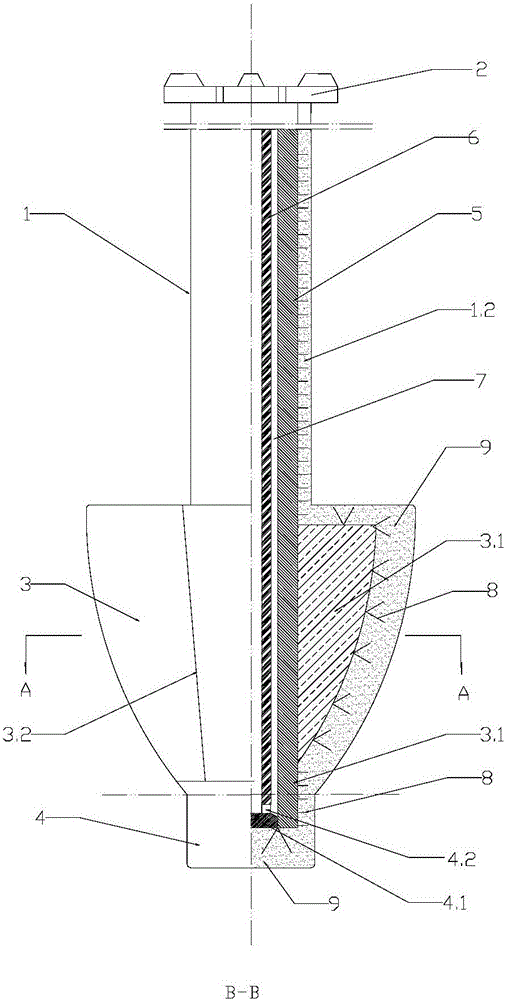
[0025] Such as figure 1 , 4 Shown in ~6: a stirrer for mechanical stirring desulfurization, which includes a stirring shaft 1 and a connecting flange 2 arranged above the stirring shaft 1, the lower end of the stirring shaft 1 is sequentially provided with 2 to 4 stirring blades 3 and The stabilizer 4, the current stabilizer 4 is a rotating body structure, the diameter of the current stabilizer 4 is constant downward along the axial direction of the current stabilizer, and the bottom of the current stabilizer 4 is a planar structure.

[0026] The inner layer of the stirring shaft 1, the stirring blade 3 and the stabilizer 4 is a hollow metal tube core 5, the top of the hollow metal tube core 5 is connected with the connecting flange 2, and a metal plug 4.1 is welded on the inner wall of the lower end of the hollow metal tube core 5, The hollow metal tube core 5 is inserted with an air-cooled pipe 6, the top of the air-cooled pipe 6 is connected to the connecting flange 2, the...

Embodiment 2

[0032] Such as figure 2 , 4 Shown in ~ 6: the structure of the agitator of this embodiment and embodiment 1 is basically the same, the difference is:

[0033] The diameter of the flow stabilizer 4 gradually decreases downward along the axial direction of the flow stabilizer, and the bottom of the flow stabilizer is a plane; the outer surface of the refractory working lining 9 at the stirring blade is an inclined surface. The outer surface of the metal core 3.1 of the stirring blade is a corresponding slope.

Embodiment 3

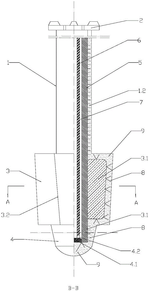
[0035] Such as Figure 3-6 Shown: the structure of this embodiment and embodiment 1 agitator is basically the same, and difference is:

[0036] The diameter of the flow stabilizer 4 decreases gradually downward along the axial direction of the flow stabilizer, and the bottom of the flow stabilizer 4 is a spherical crown structure.

[0037] The outer surface of the refractory lining 9 of the stirring blade 3 intersects the horizontal bottom surface of the refractory lining 9 of the stirring blade 3, and the outer surface of the metal core 3.1 of the stirring blade intersects the horizontal bottom surface of the metal core 3.1 of the stirring blade.


PUM


Abstract

The invention discloses a stirrer for realizing desulfurization by using mechanical stirring. The stirrer comprises a stirring shaft and a connecting flange, wherein the connecting flange is arranged at the upper portion of the stirring shaft; stirring blades and a stabilizer are sequentially arranged at the lower end of the stirring shaft; each of the stirring shaft, the stirring blades and the inner layer of the stabilizer is a hollow metal pipe core; the top of each hollow metal pipe core is connected with the connecting flange; a metal blocking head is arranged on the inner wall of the lower end of the hollow metal pipe core; an air cooling pipe is inserted into each hollow metal pipe core; the top end of each air cooling pipe is connected with the connecting flange; the pipe orifice at the lower end of each air cooling pipe forms an air outlet with the corresponding metal blocking head. The stirrer disclosed by the invention has the advantages of reducing the intensity of rotating vortex of liquid iron below the bottom center of the stirrer, delaying the damage progress of the stirrer, improving the comprehensive application performances of the stirrer, effectively relieving the shortcoming of short long service life of a large stirrer and realizing the comprehensive aims of prolonging the service life of the stirrer, reducing the consumption of the stirrer, improving the economical efficiency and the direct-selling property of a large liquid iron KR stirring desulfurization technology and the like.

Description

technical field [0001] The invention relates to a stirrer, in particular to a stirrer used for mechanical stirring desulfurization outside a molten iron furnace before steelmaking in a converter. Background technique [0002] The KR (Kambara Reactor) stirring desulfurization method is a desulfurization technology outside the molten iron furnace that Nippon Steel began to study in 1963 and was applied to industrial production in 1965. This desulfurization method is based on a cross-shaped leaf structure lined with refractory materials The agitator is immersed in the molten iron tank to rotate and stir the molten iron, so that the molten iron generates a vortex, and the weighed desulfurizer is added to the surface of the molten iron by the feeder, and is drawn into the molten iron by the vortex, and mixed and reacted with the high-temperature molten iron to achieve the purpose of desulfurization . The desulfurization method has the characteristics of high desulfurization effi...

Claims


Application Information

Patent Timeline
IPC IPC(8): C21C1/02
CPCC21C1/02
Inventor 欧阳德刚胡清明罗安智但斌斌李明晖曾彤
Owner 武汉钢铁有限公司
Why Eureka
Try Eureka