
Feeding mechanism of braided band sewing machine

The technology of a webbing sewing machine and a feeding mechanism, which is applied in the field of sewing machines, can solve the problems of low processing efficiency, inability to realize several webbing conveying, folding and feeding, etc., and achieve the effect of automatic feeding.

Active Publication Date: 2017-02-15
NINGBO SUPREME ELECTRONIC MASCH INC
View PDF7 Cites 5 Cited by
  • Summary
  • Abstract
  • Description
  • Claims
  • Application Information

AI Technical Summary

Problems solved by technology

The ribbon loom machine automatically cuts the ribbon into a set length of ribbon through the material guide mechanism, and outputs it to the stacking mechanism, and automatically folds the ribbon through the stacking mechanism to form a ribbon loop, and the feeding mechanism pushes out the last sewn ribbon loop sewing position, and at the same time send the newly folded webbing ring to the sewing position for sewing and fixing, realizing the automatic feeding, cutting, folding, unwinding and sewing of the webbing, but the webbing machine can only convey , fold, and sew a webbing
The left and right sides of the upper need to be sewn with a row of webbing loops for wearing shoelaces. The loom disclosed in this patent cannot realize the simultaneous conveying, folding and feeding of several webbings, so the processing efficiency is relatively low.

Method used


Image

  • Feeding mechanism of braided band sewing machine
  • Feeding mechanism of braided band sewing machine
  • Feeding mechanism of braided band sewing machine

Examples

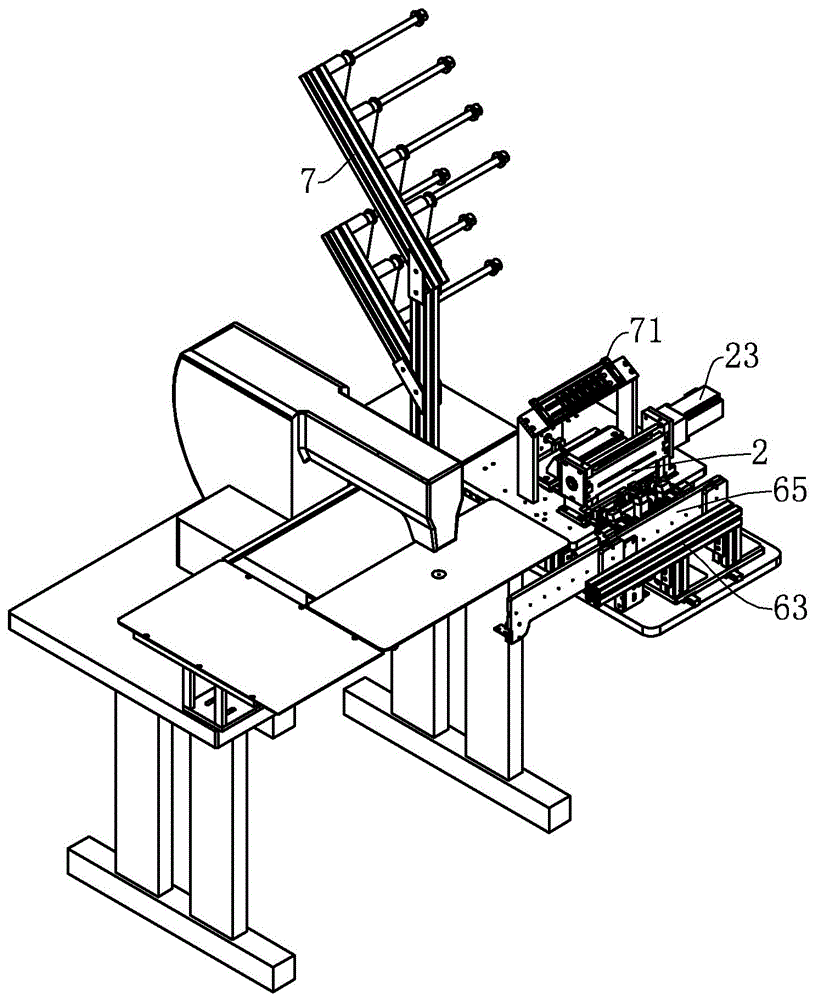
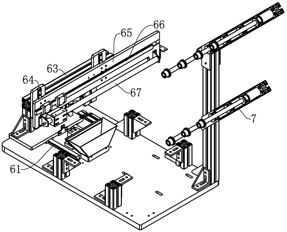
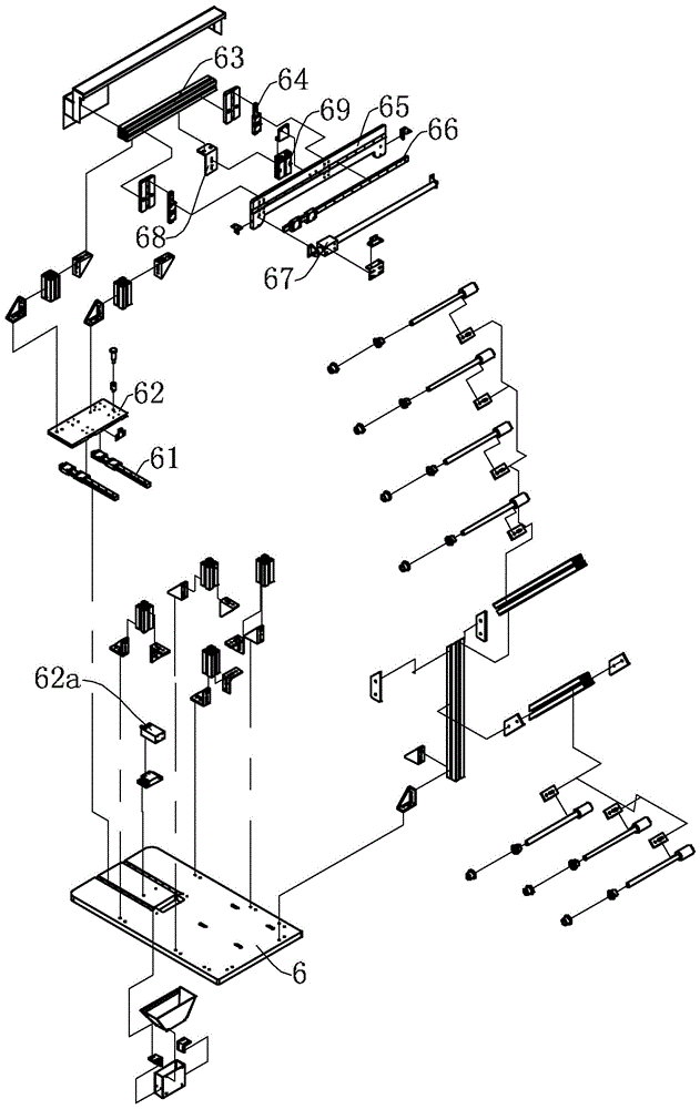

Embodiment Construction

[0025] Embodiments of the present invention will be described in further detail below in conjunction with the accompanying drawings.

[0026] Figure 1 to Figure 8 Shown is the structural representation of the present invention.

[0027] The reference signs therein are: folding material mounting seat 1, support frame 11, hot cutter 12, eager cutting mounting seat 12a, cutter seat 13, cutter driving cylinder 14, feeding guide rod 15, folding guide plate 2, feeding Material channel 21, folding material outlet 22, feeding motor 23, feeding gear 24, feeding shaft 25, first installation groove 26, feeding guide block 27, feeding guide groove 27a, lower guide block 28, Folding guide groove 28a, folding plate 3, folding mounting seat 31, folding driving cylinder 32, clamping mounting seat 4, side plate 4a, fixed convex body 4b, presser foot mounting table 4c, lower presser foot 41, Upper presser foot 42, upper presser foot drive cylinder 43, upper presser foot support 44, upper pre...


PUM


Abstract

The invention discloses a feeding mechanism of a braided band sewing machine. The feeding mechanism comprises a working platen, wherein a feeding guide rail is fixed to the working platen, a feeding fixing plate capable of sliding back and forth is arranged on the feeding guide rail, a section bar cross rod is fixed to the feeding fixing plate and is provided with a lifting guide rail, a feeding installation plate is fixed to the lifting guide rail, a material clamping installation seat capable of performing horizontal movement in the left-right direction is arranged on the feeding installation plate and is provided with a side plate, convex fixing bodies are arranged at two ends of the side plate respectively, a press pin installation table is arranged in the middle of the side plate, and a gap is reserved between the press pin installation table and any one convex fixing body, a middle press pin assembly for clamping a plurality of braided band side by side is arranged in the middle of the press pin installation table, and an auxiliary press pin assembly for clamping a single braided band is arranged in the gap.

Description

technical field [0001] The invention relates to a sewing machine, in particular to a feeding mechanism of a ribbon sewing machine. Background technique [0002] In the field of shoes, hats, clothing and home furnishing, some webbing loops are usually sewn on the product. For example, we sew webbing loops on the upper of shoes for wearing shoelaces; we sew webbing loops on curtains to facilitate hanging curtains; [0003] Existing webbing ring processing is to manually pull out the rolled webbing by a worker, cut into equal-length webbing segments, then bend the head of the webbing and sew and join the webbing body to form a webbing ring. Since they are all manual operations, the processing quality cannot be guaranteed, and the labor cost is high and the processing efficiency is low. [0004] The invention patent with the patent number of 2013107206049 discloses a ribbon loom, which includes a material guide mechanism, a material stacking mechanism and a material feeding me...

Claims


Application Information

Patent Timeline
IPC IPC(8): D05B33/00D05B29/06D05B29/12
CPCD05B29/06D05B29/12D05B33/00
Inventor 罗千
Owner NINGBO SUPREME ELECTRONIC MASCH INC
Learn More