Snow pushing device

A snow pusher and support device technology, which is applied to snow surface cleaning, construction, cleaning methods, etc., can solve the problems of easy damage of the blade or snow pusher, low reliability, poor adaptability to unevenness, etc., and achieve maintenance Convenience, high structural reliability, and the effect of improving snow removal efficiency

Inactive Publication Date: 2017-02-15
JIANGSU LIUGONG MACHINERY
View PDF8 Cites 2 Cited by
  • Summary
  • Abstract
  • Description
  • Claims
  • Application Information

AI Technical Summary

Problems solved by technology

At present, most commonly used snow removal devices use wheeled loaders (including wheel loaders, backhoe loaders, and skid steer loaders) or trucks as the main engine to perform fast-moving mechanical snow removal operations, which are usually removed with ordinary buckets. Bucket teeth, adding a blade or using an integrated snow pusher as a snow removal device to shovel or push snow, but there are problems such as easy damage to the ground, poor adaptability to local unevenness of the ground, and easy damage to the blade or snow pusher , and even cause the deformation of the structural parts of the main engine car body, affecting the normal use of the whole machine
At present, even specialized snow removal devices have problems such as low reliability, poor obstacle-crossing ability, and low single-time push snow volume.

Method used


Image

  • Snow pushing device
  • Snow pushing device
  • Snow pushing device

Examples


Embodiment 1

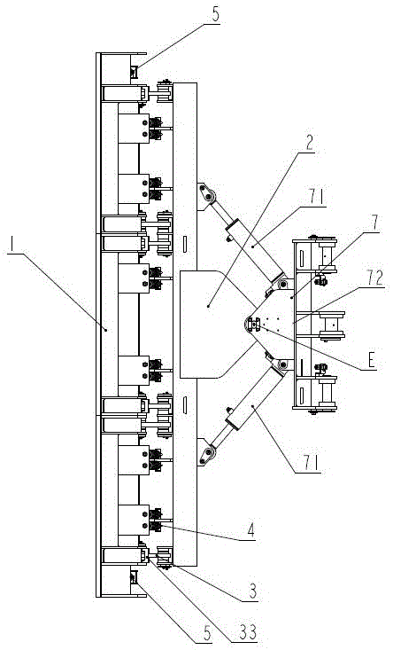
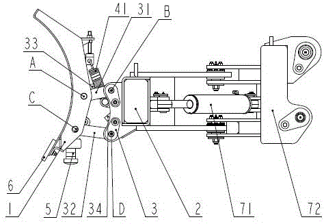
[0018] Such as figure 1 , figure 2 , image 3 As shown, a snow pusher includes a snow pusher 1, a support device 2 and a linkage mechanism 3, the snow pusher 1 is connected to the support device 2, and the other end of the support device 2 is hinged to the main machine; The snow pusher 1 is connected with the support device 2 through a link mechanism 3, and the link mechanism 3 includes an upper link 31, a lower link 32, an upper limit 33 and a lower limit 34; one end of the upper link 31 is connected to The snow pusher 1 is hinged at point A, and the other end is hinged with the support device 2 at point B; one end of the lower link 32 is hinged with the snow pusher 1 at point C, and the other end is hinged with the support device 2 2. Hinged at point D; the points A and B are above points C and D; the upper limit 33 is set on the back of the snow pusher 1 and is located within the movement range of the upper link 31. The range of motion of the upper link 31 prevents the ...

Embodiment 2

[0020] Such as figure 1 , figure 2 , image 3 As shown, a snow pusher includes a snow pusher 1, a support device 2, a link mechanism 3 and a reset device 4, the snow pusher 1 is connected to the support device 2, and the other end of the support device 2 is connected to the host The snow pusher 1 is connected to the supporting device 2 through a link mechanism 3, and the link mechanism 3 includes an upper link 31, a lower link 32, an upper limit 33 and a lower limit 34; the upper link One end of the rod 31 is hinged to the snow pusher 1 at point A, and the other end is hinged to the support device 2 at point B; one end of the lower link 32 is hinged to the snow pusher 1 at point C, and the other end is hinged to the The support device 2 is hinged at point D; the points A and B are above points C and D; the upper limit 33 is set on the back of the snow pusher 1 and is located within the range of movement of the upper link 31 , which prevents the snow pusher 1 from turning b...

Embodiment 3

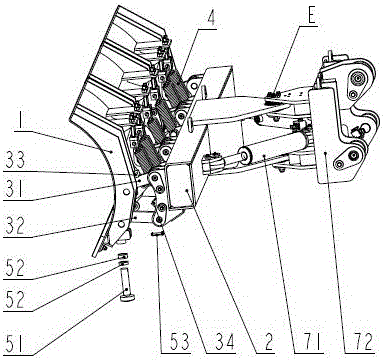
[0022] Such as figure 1 , figure 2 , image 3 , Figure 4As shown, a snow pusher includes a snow pusher 1, a support device 2, a link mechanism 3, an adjustment device 5, a movable blade 6 and a swing device 7, and the snow pusher 1 is connected to the support device 2, The other end of the support device 2 is hinged to the main engine; the snow pusher 1 and the support device 2 are connected through a link mechanism 3, and the link mechanism 3 includes an upper link 31, a lower link 32, and an upper limit 33 and the lower limit 34; one end of the upper link 31 is hinged with the snow pusher 1 at point A, and the other end is hinged with the support device 2 at point B; one end of the lower link 32 is hinged with the snow pusher 1 is hinged at point C, and the other end is hinged with the support device 2 at point D; the points A and B are above points C and D; the upper limit 33 is set on the back of the snow pusher 1 and is located at the Within the range of motion of t...


PUM


Abstract

The invention discloses a snow pushing device comprising a snow pushing board and a supporting device. The snow pushing board is connected with the supporting device, and the other end of the supporting device is connected with a main engine in a hinged mode; the snow pushing board is connected with the supporting device through a connecting rod mechanism, and the connecting rod mechanism comprises an upper connecting rod, a lower connecting rod, an upper limiting position and a lower limiting position; one end of the upper connecting rod and the snow pushing board are hinged at a point A, and the other end of the upper connecting rod and the supporting device are hinged at a point B; one end of the lower connecting rod and the snow pushing board are hinged at a point C, and the other end of the lower connecting rod and the supporting device are hinged at a point D; the point A and the point B are both arranged above the point C and thepoint D; the movement range of the upper connecting rod is limited by the upper limiting position so that backward turning of the snow pushing board can be avoided; and the movement range of the lower connecting rod is limited by the lower limiting position so that forward turning of the snow pushing board can be avoided. The snow pushing device has the beneficial effects of being capable of quickly passing ground obstacles, and achieving large snow pushing quantity at a time and high reliability.

Description

technical field [0001] The patent of the present invention relates to a snow removal device, in particular to a segmented and independent snow removal device for crossing obstacles with a snow pusher, which belongs to the technical field of construction machinery. Background technique [0002] Most of the snow removal devices are used in urban roads and highways that affect people's daily travel, and are widely used by municipal departments and sanitation departments. At present, most commonly used snow removal devices use wheeled loaders (including wheel loaders, backhoe loaders, and skid steer loaders) or trucks as the main engine to perform fast-moving mechanical snow removal operations, which are usually removed with ordinary buckets. Bucket teeth, adding a blade or using an integrated snow pusher as a snow removal device to shovel or push snow, but there are problems such as easy damage to the ground, poor adaptability to local unevenness of the ground, and easy damage ...

Claims


Application Information

Patent Timeline
Patent Type & Authority Applications(China)
IPC IPC(8): E01H5/06
CPCE01H5/06E01H5/065
Inventor 李光明陈建军徐彩云刘强李盛龙
Owner JIANGSU LIUGONG MACHINERY
Why Eureka
Try Eureka