Oil pump noise test device and test method

A technology of testing equipment and testing methods, used in pump testing, mechanical equipment, liquid variable capacity machinery, etc.

Active Publication Date: 2017-02-15
UNITED AUTOMOTIVE ELECTRONICS SYST
View PDF8 Cites 3 Cited by
  • Summary
  • Abstract
  • Description
  • Claims
  • Application Information

AI Technical Summary

Problems solved by technology

[0003] The technical problem to be solved by the present invention is to ac

Method used


Image

  • Oil pump noise test device and test method
  • Oil pump noise test device and test method
  • Oil pump noise test device and test method

Examples


Embodiment 1

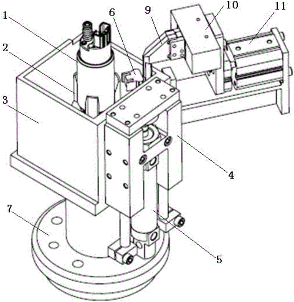
[0071] Such as figure 1 As shown, the oil pump noise test equipment includes a base support frame 2, a base support cylinder 5, and a vibration sensor unit 6;

[0072] The upper end of the oil pump 1 to be tested is suspended and fixed;

[0073] The base support frame 2 moves up and down with the expansion and contraction of the base support cylinder 5 push rod;

[0074] When the base support frame 2 moves to the upper end, it supports the oil pump 1 to be tested;

[0075] When the base support frame 2 moves to the lower end, the oil pump 1 to be tested is separated from the base support frame 2 and is in a suspended state;

[0076] The vibration sensor unit 6 can be assembled and fixed on the casing of the oil pump 1 to be tested;

[0077] The vibration sensor unit 6 is used to detect and output vibration signals.

[0078] In the oil pump noise testing equipment of Embodiment 1, when preparing for the noise test of the oil pump 1 to be tested, the ejector rod of the base ...

Embodiment 2

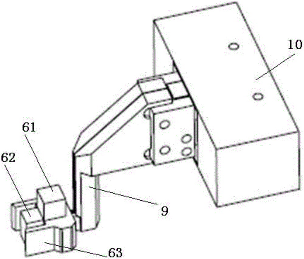
[0080] Based on the oil pump noise test equipment of embodiment one, such as figure 2 As shown, the vibration sensor unit 6 includes an acceleration sensor 61, a magnet 62, and a bracket 63;

[0081] Both the acceleration sensor 61 and the magnet 62 are installed and fixed on the bracket 63;

[0082] The casing of the oil pump to be tested is made of magnetically conductive material;

[0083] The vibration sensor unit 6 is installed and fixed on the casing of the oil pump 1 to be tested through the combination of the adsorption force of the magnet 62 .

[0084] Preferably, the casing of the oil pump 1 to be tested is cylindrical, and the matching surface between the front end of the vibration sensor unit 6 and the casing of the oil pump 1 to be tested is an arc surface.

[0085] Preferably, the magnet 62 is fixed on the front end of the bracket 63; the magnet 62 and the front end of the bracket 63 jointly constitute the mating surface between the front end of the vibration ...

Embodiment 3

[0088] Based on the first embodiment, the oil pump noise testing equipment also includes an oil supply tank 3, a guide block 4, and a flange 7;

[0089] The flange 7 is used to be fixed on the fuel tank;

[0090] The oil tank 3 is fixed on the flange 7;

[0091] The guide block 4 is fixed on the outer wall of the oil tank 3;

[0092] The base support cylinder 5 is fixed on the flange 7 , and the push rod of the base support cylinder 5 moves telescopically along the guide rail of the guide block 4 .

[0093] Preferably, the guide block 4 is an I-shaped guide block.

[0094] In the oil pump noise testing equipment of Embodiment 3, the ejector rod of the base support cylinder 5 moves up and down along the guide rail of the guide block 4, driving the oil pump support base 2 to stably support the oil pump 1 to be tested, or to leave the oil pump 1 to be tested smoothly to ensure that the oil pump to be tested is in the dangling state.


PUM


Abstract

The invention discloses an oil pump noise test device. The device comprises a base supporting frame, a base supporting air cylinder and a vibration sensor unit; the upper end of an oil pump to be tested is hung and fixed, the base supporting frame vertically moves along with the telescopic motion of an ejector rod of the base supporting air cylinder, and when the base supporting frame moves to the upper end, the oil pump to be tested is supported; when the base supporting frame moves to the lower end, the oil pump to be tested is separated from the base supporting frame and is in the midair-suspending state; and the vibration sensor unit can be mounted on and fixed to a shell of the oil pump to be tested in a combined manner, and the vibration sensor unit is used for detecting output vibration signals. The invention further discloses an oil pump noise test method. According to the oil pump noise test device and test method, the actual level of the noise of the oil pump to be tested can be accurately reflected.

Description

technical field [0001] The invention relates to vehicle performance testing technology, in particular to an oil pump noise testing device and testing method. Background technique [0002] In recent years, the performance requirements of the oil pump in the vehicle have been gradually increased by the OEMs. The noise performance during the working process of the oil pump, as a key indicator of the performance of the vehicle, has been paid more and more attention by the OEMs. The index test related to noise has always been a difficult problem in the automobile manufacturing industry. The traditional test method is to judge the noise level of the oil pump by human ears when the locomotive is idling after the oil pump is installed on the vehicle. This method not only cannot accurately reflect the actual level of the noise of the oil pump, but even if the oil pump is found to have noise problems, the product has already been loaded, and it is more complicated to replace it. Co...

Claims


Application Information

Patent Timeline
IPC IPC(8): F04B51/00
CPCF04B51/00
Inventor 代华斌李建国李兵
Owner UNITED AUTOMOTIVE ELECTRONICS SYST
Why Eureka
Try Eureka