Internal oil blocking structure of compressor and compressor with the oil blocking structure

A technology for compressors and components, which is applied to the field of internal oil blocking structures of compressors, can solve problems such as poor oil blocking effect of an oil blocking plate, and achieve the effects of good oil blocking effect, convenient manufacturing and simple structure.

Active Publication Date: 2018-07-03
GREE ELECTRIC APPLIANCES INC +1
View PDF8 Cites 0 Cited by
  • Summary
  • Abstract
  • Description
  • Claims
  • Application Information

AI Technical Summary

Problems solved by technology

[0005] Therefore, the technical problem to be solved by the present invention is that the oil retaining effect of the oil retaining plate in the prior art is not good, so as to provide an oil retaining structure inside the compressor with a better oil retaining effect and a compressor with the oil retaining structure

Method used


Image

  • Internal oil blocking structure of compressor and compressor with the oil blocking structure
  • Internal oil blocking structure of compressor and compressor with the oil blocking structure

Examples


Embodiment Construction

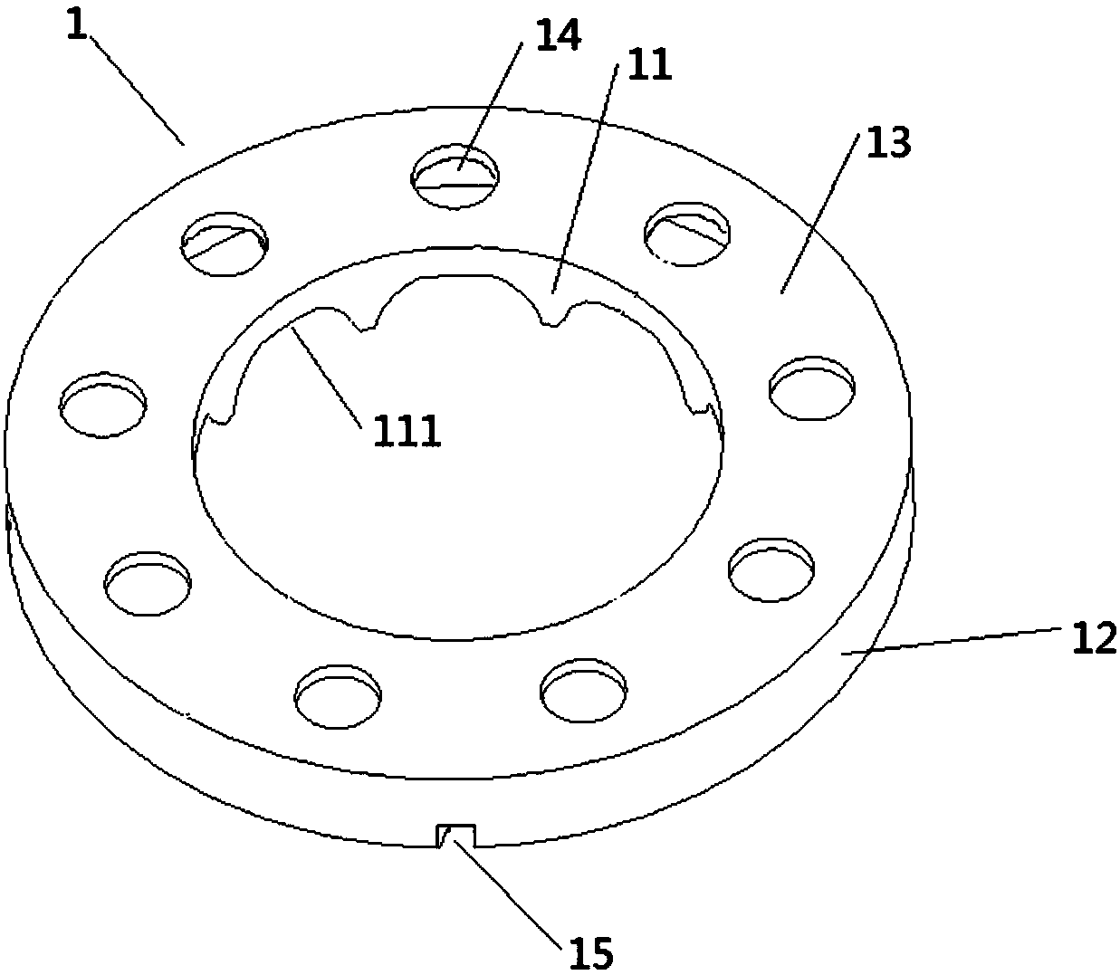
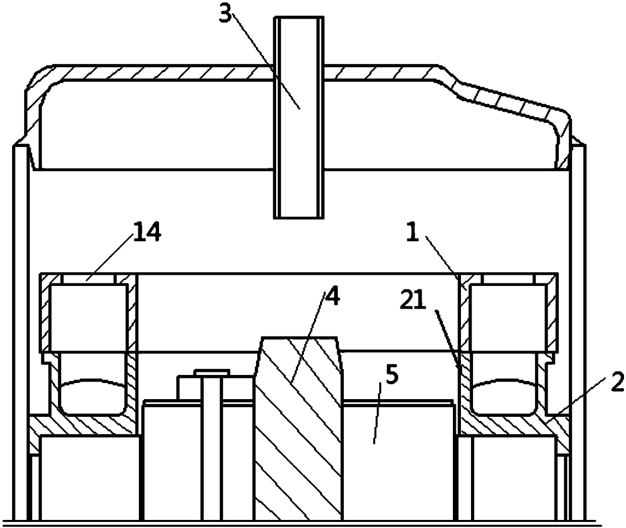
[0036] figure 1 Shown is the internal oil retaining structure of the compressor described in this embodiment, which includes an oil retaining member 1 arranged at a place where the refrigerant circulation area inside the compressor is relatively large. The oil retaining member 1 includes an inner oil retaining wall 11, an outer retaining wall The oil wall 12, the main body oil retaining wall 13, and the inner oil retaining wall 11 cooperate with the inner side of the end of the stator insulating frame 21. The inner oil retaining wall 11 is provided with a number of arc-shaped gaps 111 and the end of the stator insulating frame 21. The inner tooth guards are engaged with each other; the outer oil retaining wall 12 is fixedly matched with the outside of the end of the stator insulating frame 21, and the outer oil retaining wall 12 is provided with one or more correspondingly, on the outer end surface of the stator insulating frame 21, a buckle matching with the card slot 15 is p...


PUM


Abstract

The invention relates to the field of air compressors, in particular to an inner oil blocking structure of a compressor and the compressor with the oil blocking structure. The inner oil blocking structure comprises an oil blocking component, the oil blocking component is arranged at the position where the refrigerant circulation area in the compressor is large, and the oil blocking component is used for stopping flowing of refrigerant fluid carrying refrigeration oil. The technical problem that in the prior art, the oil blocking effect of an oil baffle in the prior art is not good needs to be solved, and accordingly the inner oil blocking structure of the compressor and the compressor with the oil blocking structure are provided, wherein the inner oil blocking structure is better in oil blocking effect.

Description

technical field [0001] The invention relates to the field of air-conditioning compressors, in particular to an oil retaining structure inside the compressor and a compressor with the oil retaining structure. Background technique [0002] The compressor usually includes a closed shell, a compression pump body, a motor assembly, a crankshaft, a gas-liquid separator, a suction pipe and an exhaust pipe. The stator and rotor form the motor assembly of the compressor, and the compression pump body includes a cylinder, an upper flange, a lower flange and a roller fixed on the eccentric part of the crankshaft. When working, the rotor rotates inside the stator, and drives the rollers to roll eccentrically in the cylinder through the crankshaft. Under the action of the eccentric rolling of the rollers, the low-pressure refrigerant is sucked into the cylinder through the suction pipe and compressed until it reaches the pressure When the critical pressure is exceeded, it is output to t...

Claims


Application Information

Patent Timeline
Patent Type & Authority Patents(China)
IPC IPC(8): F04C29/00
CPCF04C29/00
Inventor 韩东岳张强江胜军郑学良
Owner GREE ELECTRIC APPLIANCES INC
Why Eureka
Try Eureka