Conveying device for heating furnace

A technology of conveying device and heating furnace, applied in lighting and heating equipment, furnace, charge and other directions, can solve the problems of surface damage of steel pipes, collision of steel pipes with each other, large impact, etc., and achieve uniform heating state, stable conveying rate, and conveying rate. and the effect of

Inactive Publication Date: 2017-02-15
长兴吉成工业炉有限公司
View PDF5 Cites 4 Cited by
  • Summary
  • Abstract
  • Description
  • Claims
  • Application Information

AI Technical Summary

Problems solved by technology

[0002] Conveyor equipment is widely used in streamlined production lines. In actual production, due to the limited area of ​​the workshop, it is often necessary to have a steering design for the conveying equipment. This is especially common in steel pipe production workshops. Due to the length limitation of the steel pipe itself, ordinary steering equipment Can not play a very good effect, the existing technology mainly adopts the method of shifting fork to steer the steel pipe, but the method of shifting fork has the following disadvantages so that the effect is not ideal in the process of actual use. First, the shifting fork The structure often allows the steel pipe to fall during the process of lowering the steel pipe, causing the surface of the steel pipe to collide with the loading surface of the conveying equipment, but the surface of the steel pipe is damaged; If it is too large, the variable speed action is difficult to efficiently cooperate with other uniform speed conveying equipment; thirdly, the shift fork structure requires horizontal conveying equipment to cooperate with it, which increases the difficulty of speed coordination between the shift fork structure and other conveying equipment, otherwise the steel pipe is easy to Collision with each other causing surface damage

Method used


Image

  • Conveying device for heating furnace
  • Conveying device for heating furnace
  • Conveying device for heating furnace

Examples


Embodiment Construction

[0021] The present invention will be further described in detail below in conjunction with the drawings.

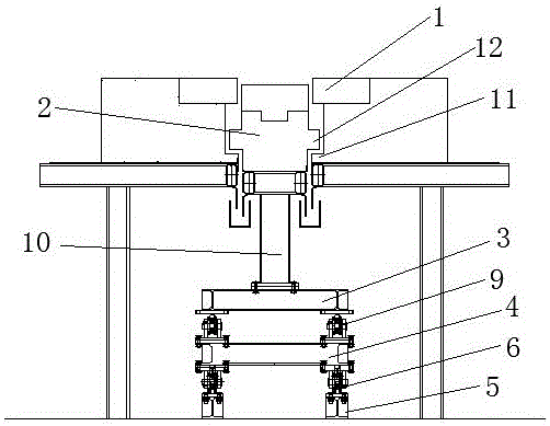
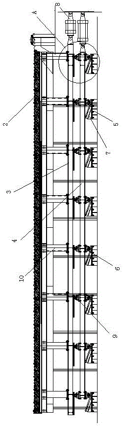
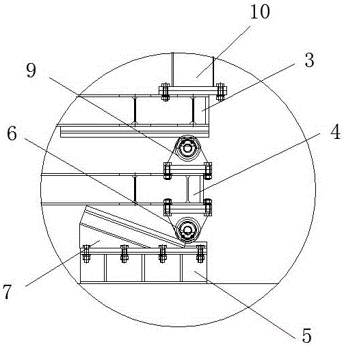
[0022] Such as Figure 1 to Figure 3 As shown, the embodiment of the present invention includes a supporting table 1 and a conveying table 2, a first moving rack 3, and a second moving rack 4 arranged parallel to each other. The conveying table 2 is fixed above the first moving rack 3, and the first moving rack 3 is slidably arranged above the second moving frame 4, there are more than three linearly aligned sliding seats 5 arranged under the second moving frame 4, and the bottom of the second moving frame 4 is provided with more than three first sliding seats that cooperate with the sliding seats 5. A pulley 6, the sliding seat 5 is provided with an inclined platform 7, and the inclined surface of the inclined platform 7 is set toward the first pulley 6, and the ends of the first moving frame 3 and the second moving frame 4 are connected with a telescopic cylinder 8 for pro...


PUM


Abstract

Disclosed is a conveying device for a heating furnace. The conveying device comprises supporting tables, a conveying table, a first moving rack and a second moving rack. The conveying table, the first moving rack and the second moving rack are arranged in parallel; the conveying table is arranged above the first moving rack in a fixed connection mode; the first moving rack is arranged above the second moving rack in a sliding mode; a plurality of linearly aligned sliding seats are disposed below the second moving rack; a plurality of first pulleys matched with the sliding seats are disposed at the bottom of the second moving rack; inclined tables are disposed on the sliding seats; and the inclined surfaces of the inclined tables face the first pulleys. The conveying device for the heating furnace has the advantages of being high in conveying rate and stable, avoiding damage to the surface of a steel pipe and the like.

Description

Technical field [0001] The invention relates to the field of logistics equipment, in particular to a conveying device for a heating furnace. Background technique [0002] Conveying equipment is widely used in streamlined production lines. In actual production, due to the limited area of ​​the plant, it is often necessary for the conveying equipment to have a steering design. This is especially common in steel pipe production workshops. Due to the length limitation of the steel pipe itself, ordinary steering equipment is Cannot achieve good results. The prior art mainly uses shift forks to transfer steel pipes. However, the shift fork has the following shortcomings, which make the effect in actual use unsatisfactory. First, shift forks The structure often allows the steel pipe to fall during the process of lowering the steel pipe, causing the surface of the steel pipe to collide with the loading surface of the conveying equipment, but the surface of the steel pipe is damaged; seco...

Claims


Application Information

Patent Timeline
Patent Type & Authority Applications(China)
IPC IPC(8): F27B9/14
CPCF27B9/14F27M2001/1556
Inventor 罗来军严霆彭李伟
Owner 长兴吉成工业炉有限公司
Why Eureka
Try Eureka