One-time composite structure gas blaster and manufacturing method thereof

A composite structure, one-time technology, applied in the direction of blasting, blasting barrels, weapon accessories, etc., can solve the problems of high labor costs and consumable costs, easy deformation of the tube body, and difficult maintenance

Inactive Publication Date: 2017-02-15
郭远军
View PDF1 Cites 0 Cited by
  • Summary
  • Abstract
  • Description
  • Claims
  • Application Information

AI Technical Summary

Problems solved by technology

[0011] The object to be realized by the present invention is: to reduce the weight of the existing gas blaster, reduce the production cost, and compare with the prior art, the storage energy of the steel cylinder with the same size is larger, simplify the inflation process, and overcome the sealing problem; to solve the above-mentioned background technology Existing in the existing gas blasters: 1. The thickness of the blasting cylinder is 8-60mm, and the density of the steel is high, and the gas blasters generally have the problems of heavy weight, time-consuming and laborious transportation and i...

Method used


Image

  • One-time composite structure gas blaster and manufacturing method thereof
  • One-time composite structure gas blaster and manufacturing method thereof
  • One-time composite structure gas blaster and manufacturing method thereof

Examples


Embodiment 1

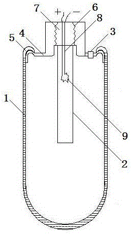
[0115] Such as figure 1 As shown, a disposable composite structure gas blaster includes an energy storage device 1, a detonating mechanism 2, an inflating mechanism 3, an energy discharge head 4, a wrapping layer 5, an internal thread 6, a sealing head 7, and a lead hole 8 and heating wire 9; the energy storage device 1 is provided with an energy discharge head 4, the energy storage device 1 fixes the energy discharge head 4 through the wrapping layer 5, and the middle part of the energy discharge head 4 is provided with an internal thread 6 and a sealing head 7 matched therewith The lower part of the sealing head 7 is provided with an activator 201, the middle part of the sealing head 7 is provided with a lead wire hole 8, and a detonating wire 202 is arranged in the lead wire hole 8, and the detonating wire 202 is connected to both ends of the heating wire 9.

Embodiment 2

[0117] A gas blaster, comprising an energy storage device 1 and an energy discharge head 4, and one end of the energy storage device 1 is equipped with an energy discharge head 4;

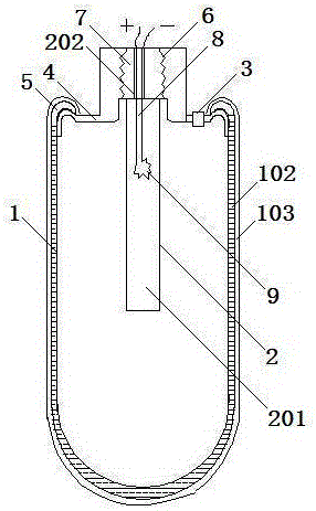
[0118] Such as figure 2 As shown, the energy storage device 1 includes a mesh layer 102 and a hardened layer 103, and the mesh layer 102 and the hardened layer 103 are distributed sequentially from the inside to the outside.

Embodiment 3

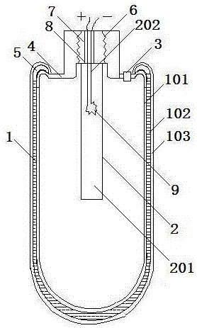
[0120] Such as image 3 As shown, the energy storage device 1 includes a base layer 101 , a mesh layer 102 and a hardened layer 103 , and the base layer 101 , the mesh layer 102 and the hardened layer 103 are distributed sequentially from inside to outside.


PUM

PropertyMeasurementUnit
Compressive strengthaaaaaaaaaa
Thicknessaaaaaaaaaa
Thicknessaaaaaaaaaa

Abstract

The invention discloses a one-time composite structure gas blaster which comprises an energy storing device 1, a detonation structure 2 and an inflation mechanism 3. The detonation structure 2 and the inflation mechanism 3 are installed at one end of the energy storing device 1, and the other end of the energy storing device 1 is sealed or integrally formed. The energy storing device 1 is made of a material with the compressive strength larger than 345 Mpa. The one-time composite structure gas blaster has the beneficial effects that the thickness is small, the weight is small, and transporting and installing are convenient; manufacturing is simple, the consumable item cost is low, and the production cost is low; inflating is fast; the sealing performance is good, the service life is long, and the cycle life is long; repair is easy after blasting deformation, the maintenance cost is extremely low, and on-site repair can be achieved; the stability of the blaster after energy storage is good; the yield is high; and the manufacturing technology is simple.

Description

technical field [0001] The invention belongs to the field of blasting, and relates to a blasting device, in particular to a gas blaster. Background technique [0002] Gas blasting technology is the use of gasification and expansion of liquid or solid substances that are easy to gasify to generate high-pressure energy, so that the surrounding medium expands to do work and cause fragmentation; gas blasting technology is widely used in mining, geological exploration, cement, steel, electric power, etc. Industry, subway and tunnel and municipal engineering, underwater engineering, and emergency rescue. At present, the equipment used in gas blasting technology is a gas blasting tube. The blasting tube mainly includes an inflatable structure, a detonating structure, an expansion medium storage structure and a sealing structure. It has the following disadvantages: [0003] At present, the expansion medium storage structure used in gas blasting technology is mainly a steel pipe or ...

Claims


Application Information

Patent Timeline
IPC IPC(8): F42D1/00E21C37/14F42B3/04F42B3/28
CPCF42D1/00E21C37/14F42B3/04F42B3/28
Inventor 郭远军
Owner 郭远军
Why Eureka
Try Eureka