Liquid crystal display panel and liquid crystal alignment method thereof

A liquid crystal display panel and liquid crystal alignment technology, applied in optics, instruments, nonlinear optics, etc., can solve the problems of uneven brightness of display panels and decreased light transmittance.

Inactive Publication Date: 2017-02-15
AU OPTRONICS CORP
View PDF11 Cites 16 Cited by
  • Summary
  • Abstract
  • Description
  • Claims
  • Application Information

AI Technical Summary

Problems solved by technology

[0004] One of the objectives of the present invention is to provide a liquid crystal display panel and a liquid crystal alignment method thereof, which forms a polymer alignment layer on only one side of the substrate, and uses a self-assembly vertical alignment (self-assembly vertical alignment) additive (additive), To improve the problem of light transmittance decrease and uneven brightness of the display panel caused by panel bending or misalignment

Method used


Image

  • Liquid crystal display panel and liquid crystal alignment method thereof
  • Liquid crystal display panel and liquid crystal alignment method thereof
  • Liquid crystal display panel and liquid crystal alignment method thereof

Examples


Embodiment Construction

[0038] In order to enable those skilled in the art to have a better understanding of the present invention, the preferred embodiments of the present invention are enumerated below, together with the accompanying drawings, the composition and technical effects of the present invention are described in detail.

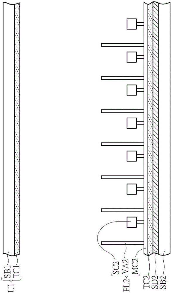
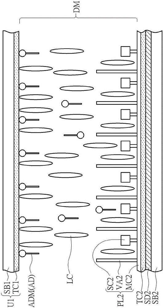
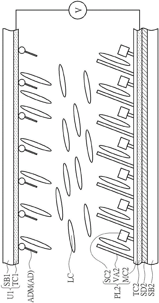
[0039] Please refer to Figure 1 to Figure 5 , Figure 1 to Figure 5 a schematic diagram showing the first embodiment of the alignment method of the liquid crystal display panel of the present invention, and Figure 5 A schematic cross-sectional view of the first embodiment of the liquid crystal display panel structure of the present invention is shown. According to the first embodiment of the alignment method of the liquid crystal display panel of the present invention, first as figure 1 As shown, a first substrate unit U1 is provided, wherein the first substrate unit U1 includes a first substrate SB1. On the other hand, the method of this embodiment includes providin...


PUM

PropertyMeasurementUnit
mean roughnessaaaaaaaaaa

Abstract

The invention provides a liquid crystal display panel and a liquid crystal alignment method thereof. The liquid crystal display panel comprises a first substrate unit, a second substrate unit and a display dielectric layer. The first substrate unit includes a first substrate and a first conducting layer, wherein the surface of the first conducting layer has a first surface root-mean-square roughness. The second substrate unit includes a second substrate and a second conducting layer, wherein the surface of the second conducting layer has a second surface root-mean-square roughness. The display dielectric layer is located between the first and second substrates and comprises a plurality of liquid crystal molecules. The liquid crystal molecules located on the surface of one of the first and second conducting layers have tilt angles, and liquid crystal molecules located on the surface of the other one of the first and second conducting layers don't have tilt angles. The first surface root-mean-square roughness is less than the second surface root-mean-square roughness.

Description

technical field [0001] The invention relates to a liquid crystal display panel and a liquid crystal alignment method thereof, in particular to a liquid crystal display panel capable of avoiding uneven brightness caused by dislocation and a liquid crystal alignment method thereof. Background technique [0002] Liquid crystal display panels have been widely used in various electronic products, such as smart phones, notebook computers, and tablet PCs, due to their advantages of thinness, lightness, small size, and energy saving. Recently, liquid crystal display panels Panels are not limited to flat displays, and a large number of curved liquid crystal display panels have been developed and developed, such as curved TVs (curve TVs), curved mobile phones (curve smart phones), and curved screens (curve monitors). viewing angles and surround effects. [0003] However, when the liquid crystal display panel technology is applied to a curved liquid crystal display panel, the aligned ...

Claims


Application Information

Patent Timeline
Patent Type & Authority Applications(China)
IPC IPC(8): G02F1/1337
CPCG02F1/133711G02F1/133788G02F1/133773
Inventor 郑德胜赵韦善王惠民
Owner AU OPTRONICS CORP
Why Eureka
Try Eureka