Eureka AIR delivers breakthrough ideas for toughest innovation challenges, trusted by R&D personnel around the world.

Buck-boost constant current circuit and output current sampling method thereof

A technology of constant current circuit and buck-boost technology, which is applied in the field of constant current circuit, can solve the problems of complex system stability, sensitive layout, high input voltage, etc., and achieve the effect of constant current control of the system, easy stability of the system, and simple design

Inactive Publication Date: 2017-02-15
SHENZHEN OCX SEMICON CO LTD +1
View PDF7 Cites 1 Cited by
  • Summary
  • Abstract
  • Description
  • Claims
  • Application Information

AI Technical Summary

Problems solved by technology

However, in some cases, the above circuit has a disadvantage: that is, the withstand voltage of the constant current control IC is required to be greater than or equal to the input voltage VIN
In some applications, the input voltage may be very high, and it is difficult to implement such a constant current control IC with common processes
In addition, this sampling is more sensitive to layout
In addition, when the input or output voltage range is wide, the stability of the system is more complicated. If the internal compensation of the constant current control IC needs to occupy a large chip area, if the external compensation of the constant current control IC needs to increase the external components so that increase cost

Method used


Image

  • Buck-boost constant current circuit and output current sampling method thereof
  • Buck-boost constant current circuit and output current sampling method thereof
  • Buck-boost constant current circuit and output current sampling method thereof

Examples


Embodiment Construction

[0028] In order to make the object, technical solution and advantages of the present invention clearer, the present invention will be further described in detail below in conjunction with the accompanying drawings and embodiments. It should be understood that the specific embodiments described here are only used to explain the present invention, not to limit the present invention.

[0029] It should be noted that when an element is referred to as being “fixed on” or “disposed on” another element, it may be directly on the other element or there may be an intervening element at the same time. When an element is referred to as being "connected to" another element, it can be directly connected to the other element or intervening elements may also be present.

[0030] It should also be noted that the orientation terms such as left, right, up, and down in the embodiments of the present invention are only relative concepts or refer to the normal use state of the product, and should ...


PUM


Abstract

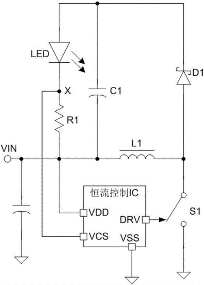
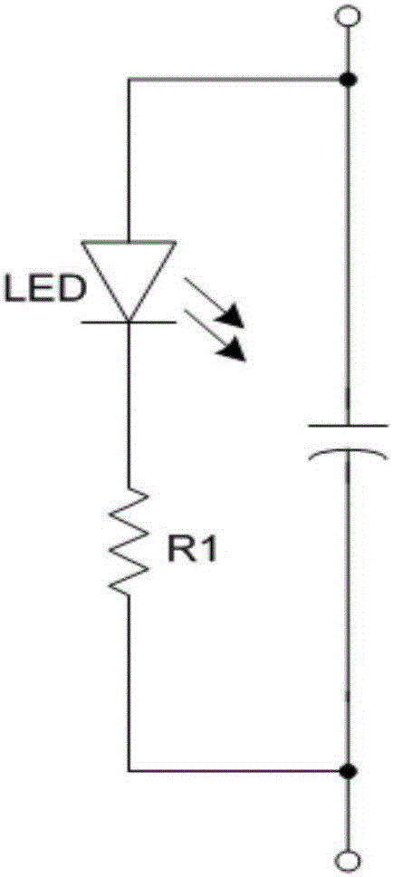
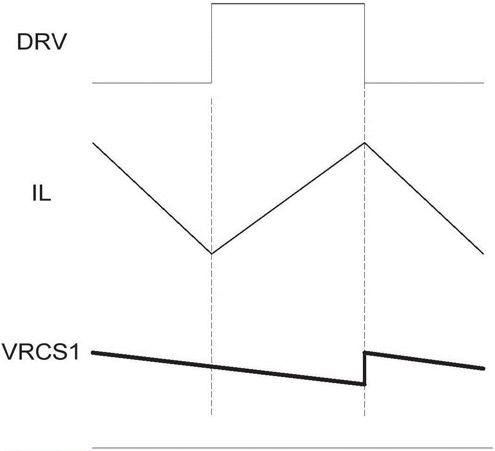
The present invention discloses a buck-boost constant current circuit and an output current sampling method thereof. The circuit comprises a constant current control IC, the VDD pin of the constant current control IC is connected with a voltage input end VIN, the VSS pin of the constant current control IC is connected with a chip ground, the DRV pin of the constant current control IC is an output end to control the connection and disconnection of the S1, the output load is connected in parallel with the C1, the output load, the L1, the D1 and the R1 are connected in series to form a closed loop, and the R1 is connected between the VCS of the constant current control IC and the VDD pin or between the VCS pin and the VSS pin. The buck-boost constant current circuit can realize the system constant current control in the condition that the input voltage is very wide.

Description

technical field [0001] The invention belongs to the technical field of constant current circuits, in particular to a buck-boost constant current circuit and an output current sampling method thereof. Background technique [0002] The buck-boost constant current circuit is often used in LED driving. In this type of application, the input voltage range is wide, and the output voltage is between the minimum and maximum input voltage. The commonly used buck circuit or boost circuit cannot meet the wide input voltage. range requirements, a buck-boost structure must be used. figure 1 It is a traditional buck-boost constant current circuit; it has the advantages of simple circuit structure and few peripheral components. However, in some cases, the above-mentioned circuit has a disadvantage: that is, the withstand voltage of the constant current control IC is required to be greater than or equal to the input voltage VIN. In some applications, the input voltage may be very high, an...

Claims


Application Information

Patent Timeline
Patent Type & Authority Applications(China)
IPC IPC(8): H05B33/08H05B44/00
CPCH05B45/37Y02B20/30
Inventor 李永红
Owner SHENZHEN OCX SEMICON CO LTD
Why Eureka
Eureka Blog
Learn More