Injection molding method, screw, and injection molding machine

A technology of injection molding and screw, which is applied in the field of injection molding, can solve the problems of uneven distribution, difficult reinforcement fiber dispersion, reinforcement fiber cannot be uniformly dispersed, etc., and achieve the effect of eliminating uneven distribution

Active Publication Date: 2017-02-15
宇菱 +2
View PDF4 Cites 2 Cited by
  • Summary
  • Abstract
  • Description
  • Claims
  • Application Information

AI Technical Summary

Problems solved by technology

In order to achieve uniform dispersion, it is sufficient to increase the shearing force applied to the reinforcing fibers by making the mixing conditions strict, but excessive shearing force will lead to cutting of the reinforcing fibers
In this way, the fiber length after molding is greatly shortened compared with the original fiber length, and there is a possibility that the obtained molded product cannot satisfy desired properties (Patent Document 1)
Therefore, it is necessary to select injection molding conditions that weaken the shear force to prevent fiber breakage during mixing, but in this way, the reinforcing fibers cannot be uniformly dispersed in the fiber-reinforced resin, resulting in uneven distribution.
In addition, in order to contribute to the uniform dispersion of reinforcing fibers, there are also cases where a mechanism (feeder) for forcibly supplying reinforcing fibers into the cylinder is provided (for example, Patent Document 2), but this is not enough to dissipate the mass of reinforcing fibers eliminate
In particular, when the content of reinforcing fibers is as high as 10% or more, it becomes difficult to uniformly disperse the reinforcing fibers in the resin

Method used


Image

  • Injection molding method, screw, and injection molding machine
  • Injection molding method, screw, and injection molding machine
  • Injection molding method, screw, and injection molding machine

Examples


Embodiment Construction

[0034] Hereinafter, the present invention will be described in detail based on the embodiments shown in the drawings.

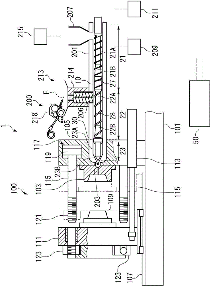
[0035] Such as figure 1 As shown, the injection molding machine 1 according to this embodiment includes a mold clamping unit 100 , a plasticizing unit 200 , and a control unit 50 that controls the operations of the above-mentioned units.

[0036] Hereinafter, the structure and operation of the mold clamping unit 100 and the outline of the structure and operation of the plasticizing unit 200 will be described, and then the process of injection molding by the injection molding machine 1 will be described.

[0037] [Structure of clamping unit]

[0038] The mold clamping unit 100 has: a fixed template 105, which is fixedly arranged on the base frame 101 and is installed by the fixed mold 103; Move in left and right directions and be installed by movable mold 109 ; On the fixed platen 105 , a hydraulic cylinder 117 for mold clamping is provided coaxially with ...


PUM


Abstract

Provided is an injection molding method that can resolve uneven reinforcing fiber distribution without applying an excessive shearing force on the reinforcing fibers. In the injection molding method for fiber-reinforced resin according to the present invention: a resin-accumulating area is provided on the downstream side of the injection completion position inside a heating cylinder (201); in the injection step of a preceding cycle, an injection pressure is applied on molten resin (Mr) occupying the resin-accumulating area; and in the plasticizing step of the following cycle, a shearing force is applied on the molten resin (Mr) that is occupying the resin-accumulating area. Applying a high injection pressure on the molten resin (Mr) occupying the resin-accumulating area impregnates molten resin (Mr) into clumped reinforcing fibers (F). Subsequently applying a shearing force in the plasticizing step of the following cycle promotes dispersion of the reinforcing fibers (F).

Description

technical field [0001] The present invention relates to injection molding of resin containing reinforcing fibers. Background technique [0002] Molded articles of fiber-reinforced resins whose strength is increased by containing reinforcing fibers are used in various applications. As a method of obtaining the molded product by injection molding, there is known a method of melting a thermoplastic resin by rotation of a screw in a cylinder constituting a plasticizing device, mixing or kneading fibers therein, and then injecting it into a mold of an injection molding machine . [0003] In order to obtain the effect of improving the strength by the reinforcing fibers, it is desirable that the reinforcing fibers be uniformly dispersed in the resin. In order to achieve uniform dispersion, it is sufficient to increase the shearing force applied to the reinforcing fibers by making the mixing conditions strict, but too strong a shearing force may cause cutting of the reinforcing fi...

Claims


Application Information

Patent Timeline
Patent Type & Authority Applications(China)
IPC IPC(8): B29C45/47B29B7/90
CPCB29B7/90B29B7/905B29C45/0005B29C45/50B29C45/60B29K2105/12
Inventor 苅谷俊彦信田宗宏户田直树木下清山口雄志
Owner 宇菱
Why Eureka
Try Eureka