Regulator flow damping

A technology of flow regulator and regulating valve, which is applied in the fuel valve, transportation and packaging of machine/engine, turbine/propulsion device, etc., can solve problems such as excess, and achieve the effect of reducing leakage sensitivity and improving pollution resistance.

Active Publication Date: 2017-02-15
WOODWARD GOVERNOR CO
View PDF2 Cites 0 Cited by
  • Summary
  • Abstract
  • Description
  • Claims
  • Application Information

AI Technical Summary

Problems solved by technology

However, no-flow orifice repression is proportional to the square of the valve velocity
As a result, the orifice provides no damping when the valve is at rest (e.g., valve velocity equals zero), but can over dampen the valve during periods of larger disturbances

Method used


Image

  • Regulator flow damping
  • Regulator flow damping
  • Regulator flow damping

Examples


Embodiment Construction

[0020] This document describes systems and techniques for regulating fluid flow with a dampened response. A flow regulator valve can maintain fluid flow provided at the inlet of the flow regulator. Two choke schemes for flow regulator systems include the use of laminar leak path chokes or orifices in non-flow lines.

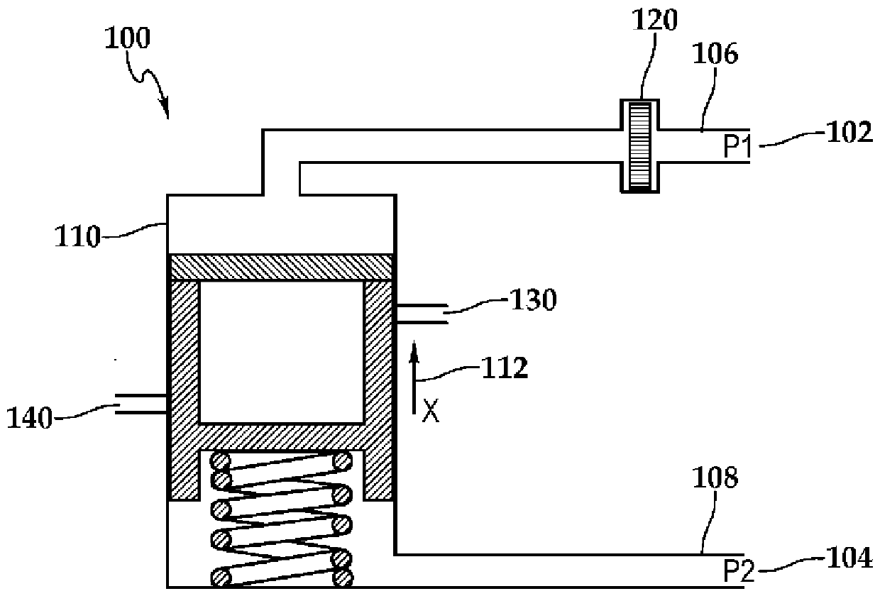
[0021] figure 1 is a schematic diagram of a prior art fluid flow regulator 100 using laminar flow leak path chokes. Regulator 100 includes two different pressure signals at 102 and 104 . The fluid at 102 is fluidly connected to fluid passage 106 and the fluid at 104 is fluidly connected to fluid passage 108 .

[0022] Fluid passage 106 is fluidly connected to outlet fluid passage 108 via bypass valve 110 and laminar flow-resistance orifice 120 . Bypass valve 110 includes a plurality of ports (not shown) that fluidly connect inlet fluid passage 130 to outlet fluid passage 140 . Bypass valve 110 exhibits a regulator speed, generally indicated by arrow 112 . ...


PUM


Abstract

The subject matter of this specification can be embodied in, among other things, a method that includes providing a fluid at a fluid inlet fluidically connected to an input fluid path, providing a fluid outlet fluidically connected to an outlet fluid path, fluidically connecting the inlet fluid path to the outlet fluid path through a valve, fluidically connecting the inlet fluid and the outlet fluid through a bypass fluid path in parallel with the valve, flowing the fluid from the inlet fluid path to the outlet fluid path through the valve and the bypass fluid path at a regulated fluid flow rate, restricting fluid flow in the bypass fluid path with a first orifice, restricting fluid flow in one of the fluid inlet path or the fluid outlet path with a second orifice, and providing the fluid at the fluid outlet at an outlet fluid flow rate.

Description

[0001] Cross References to Related Applications [0002] This application claims priority to US Patent Application No. 14 / 272,085, filed May 7, 2014, the entire contents of which are hereby incorporated by reference. technical field [0003] The principles herein relate to fluid flow regulators, and more particularly to fluid flow regulators with a damped modulation response. Background technique [0004] The flow regulating valve is an integral component that provides a constant fluid flow rate to the combustion chamber as requested by external commands regardless of inlet flow at the flow regulating valve. Historically, flow regulating valves utilize laminar flow leak paths or choke through orifices in non-flowing lines. [0005] Laminar leak path rejection provides linear rejection over the entire valve speed range. However, damping is directly proportional to the kinematic viscosity of the fluid being conditioned, and thus damping is sensitive to temperature changes o...

Claims


Application Information

Patent Timeline
Patent Type & Authority Applications(China)
IPC IPC(8): F02C7/232F02C9/26
CPCF02C7/232F02C9/263Y10T137/0379Y10T137/7801F02M69/54
Inventor B.J.斯诺格拉斯P.J.谢菲尔B.K.劳弗
Owner WOODWARD GOVERNOR CO
Why Eureka
Try Eureka