Forming roller of equipment for producing monowing labyrinth type drip tapes

A labyrinth, drip irrigation belt technology, applied in the direction of presses, presses, manufacturing tools, etc. using rotating pressure components, can solve the problems of increased material cost, high processing difficulty, imprints on the joints of flat parts, etc., to improve production. Efficiency, reduced rotational inertia, increased stability effect

Active Publication Date: 2015-02-04
TANGSHAN ZHIFU PLASTIC MACHINERY
View PDF4 Cites 0 Cited by
  • Summary
  • Abstract
  • Description
  • Claims
  • Application Information

AI Technical Summary

Problems solved by technology

This form of forming wheel has the following disadvantages: ①The surface of the produced single-wing labyrinth drip irrigation belt product is not smooth, and there are marks on the joints of flat parts; there is a concentricity error in the assembly of the forming wheel, and the labyrinth pattern on the surface after grinding Different shades lead to poor drip uniformity of drip irrigation tape products; ②If you need to produce drip irrigation tapes with different labyrinth widths, you must purchase raw materials of different specifications when processing the forming wheel, which increases the material cost; ③Labyrinth patterns on both sides of the forming wheel The pattern of the water inlet and outlet needs to be processed separately, and finally assembled together. The processing is difficult, which makes the production efficiency of the forming wheel low; The cooling effect on the forming wheel and the drip irrigation belt is poor, and it is necessary to prolong the cooling time to achieve the purpose of complete cooling, thus restricting the production speed of the equipment

Method used


Image

  • Forming roller of equipment for producing monowing labyrinth type drip tapes
  • Forming roller of equipment for producing monowing labyrinth type drip tapes
  • Forming roller of equipment for producing monowing labyrinth type drip tapes

Examples


Embodiment Construction

[0017] The present invention is further described below in conjunction with the examples, the purpose is only to better understand the content of the present invention. Therefore, the examples given do not limit the protection scope of the present invention.

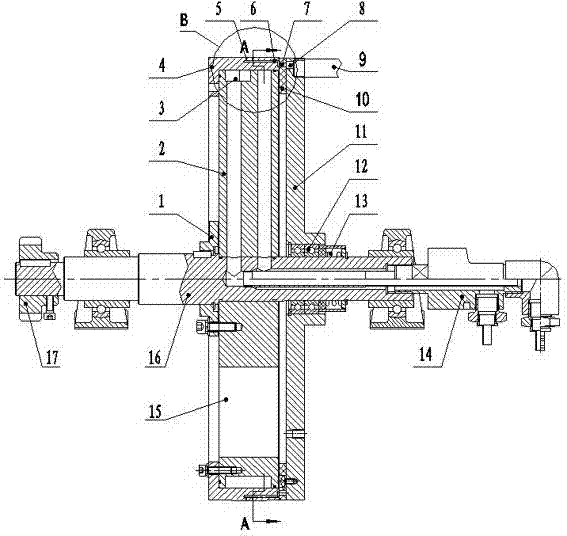
[0018] Referring to the accompanying drawings, this forming wheel for producing single-wing labyrinth drip irrigation belt equipment consists of a main shaft flange 1, a cooling body 2, a forming body 4, a friction plate 10, a compression flange 11, a pressure spring 13, a rotating shaft 16, etc. composition.

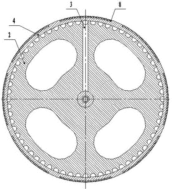
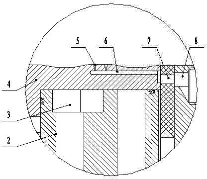
[0019] The molded body 4 is set on the outer circumference of the cooling body 2, and the outer circumference of the molded body 4 is processed with several sections of labyrinth runner patterns 5 that are symmetrical, continuous, regular, and concave. Each labyrinth channel pattern 5 on the circumferential surface is connected to each independent vacuum air channel 6, and the outer end of the forming body 4 is p...


PUM


Abstract

Disclosed is a shaping wheel for use in an apparatus for manufacturing a drip-irrigation tape with labyrinth on one side, wherein a shaping body (4) is sheathed on an outer circumference of a cooling body (2), vacuum air channels (6) independent of each other and in communication with each of labyrinth-shaped flow channel striations (5) on the outer circumferential surface are made in the shaping body (4), a friction piece (10) fixed together with a pressing flange (11) is provided on the outer side of the shaping body (4), and the pressing flange (11) is provided with a negative pressure channel (8), one end of which is in intermittent communication with the vacuum air channels (6) in the shaping body (4) via a small hole (7) on the friction piece (10), and the other end of which is in communication with a vacuum-extracting device. A labyrinth-shaped water channel (3) is made on the outer circumferential surface of the cooling body (2). The shaping wheel shapes in one go labyrinth-shaped flow channel striations (5) of a drip-irrigation tape with labyrinth on one side, guaranteeing the quality of the drip-irrigation tape article, reducing production costs and improving production efficiency.

Description

technical field [0001] The invention relates to a single-wing labyrinth drip irrigation belt production equipment, in particular to a forming wheel for producing single-wing labyrinth drip irrigation belt equipment. Background technique [0002] At present, the two labyrinth patterns of the forming wheel in the single-wing labyrinth drip irrigation belt production equipment and its inlet and outlet patterns are processed on independent parts, and through holes are processed on both sides as cooling water channels, and the parts are stacked and assembled Together, the outer surfaces are ground to achieve a flat circumferential surface. This form of forming wheel has the following disadvantages: ①The surface of the produced single-wing labyrinth drip irrigation belt product is not smooth, and there are marks on the joints of flat parts; there is a concentricity error in the assembly of the forming wheel, and the labyrinth pattern on the surface after grinding Different shades...

Claims


Application Information

Patent Timeline
Patent Type & Authority Patents(China)
IPC IPC(8): B29C59/04
CPCB30B15/34B30B3/005
Inventor 王志富
Owner TANGSHAN ZHIFU PLASTIC MACHINERY
Why Eureka
Try Eureka