Multi-target laser distance meter

A laser range finder, laser technology, applied in the field of laser range finder, can solve the problem of lack of multi-target capability, etc., and achieve the effect of simple Fourier transform, accurate distance measurement, and simple analysis

Active Publication Date: 2017-02-15
ROBERT BOSCH GMBH
View PDF10 Cites 7 Cited by
  • Summary
  • Abstract
  • Description
  • Claims
  • Application Information

AI Technical Summary

Problems solved by technology

in other words, they generally lack multi-target capabilities

Method used


Image

  • Multi-target laser distance meter
  • Multi-target laser distance meter
  • Multi-target laser distance meter

Examples


Embodiment Construction

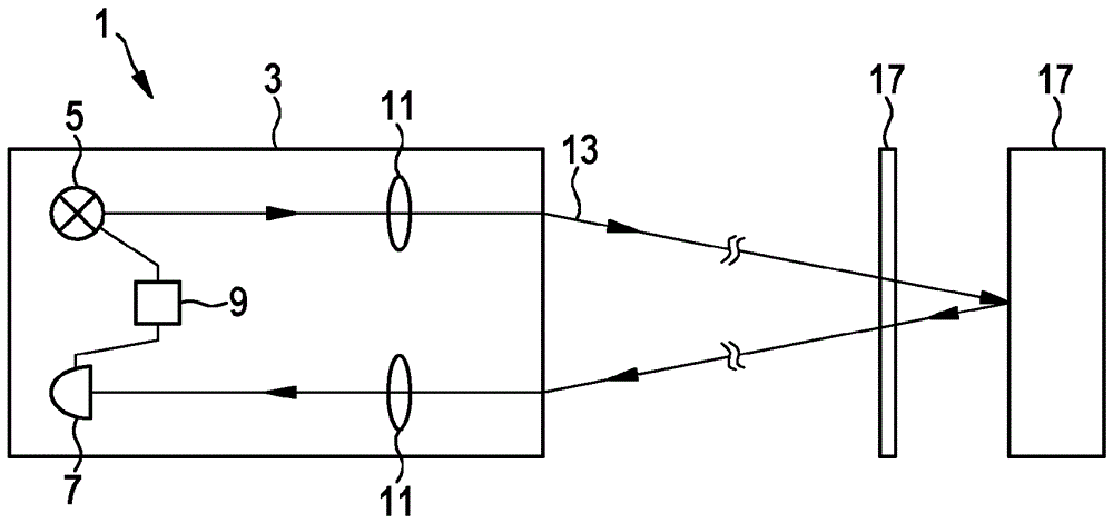
[0047] figure 1 A laser distance measuring device 1 according to an embodiment of the invention is shown. Accommodated in a common housing 3 , the laser distance measuring device 1 comprises a laser light source 5 , for example a laser diode, a light detector 7 , for example a SPAD or a SPAD array, and control and evaluation electronics 9 . Furthermore, the laser rangefinder 1 can have one or more lenses 11 in order to focus the laser beam 13 emitted by the laser light source 5, aim it at one or more target objects 15, 17 and / or to be reflected The reflected light is directed onto the detection surface of the photodetector 7 . In particular, the laser distance measuring device 1 can be designed to be small and compact enough to be used as a hand-held device.

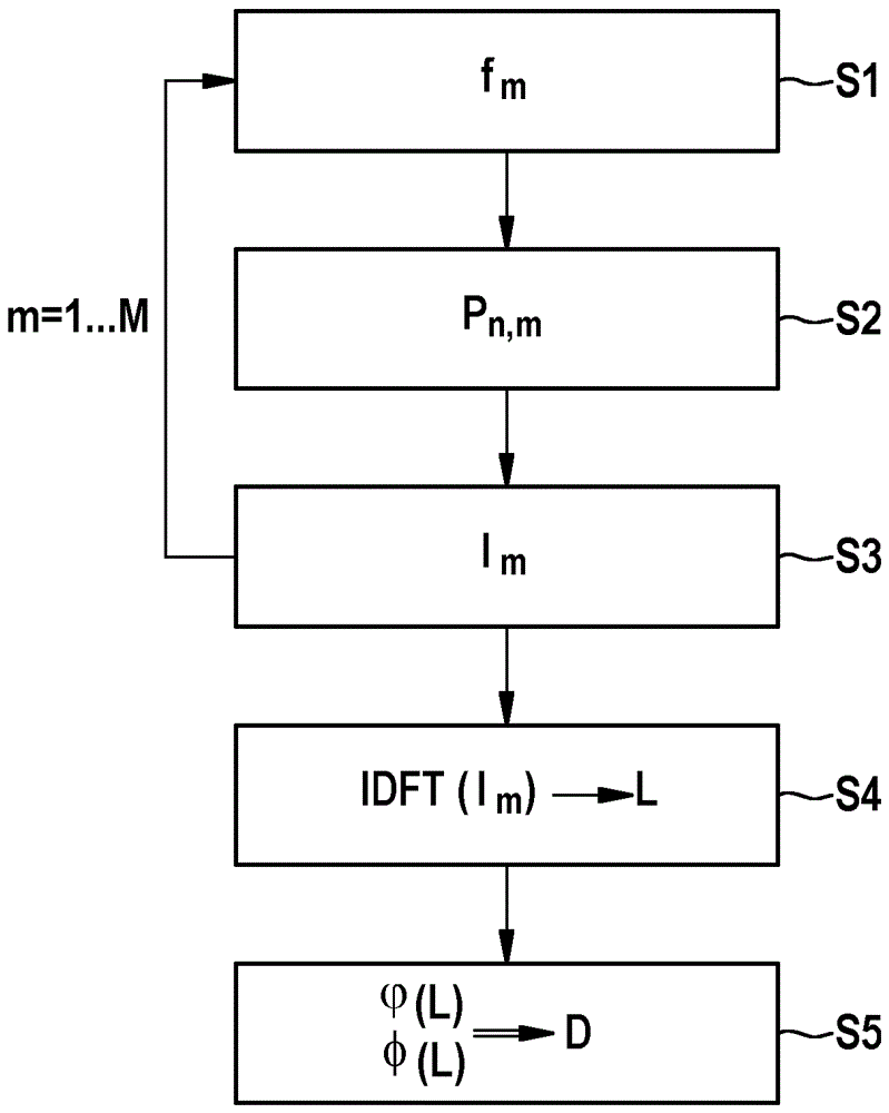
[0048] Below is an example of how the laser distance measuring device 1 can be operated with suitably adjusted control and evaluation electronics 9 . hereby refer to in figure 2 The method sequence and method steps ...


PUM


Abstract

The invention relates to a laser distance meter (1) which has a laser light source (5) for emitting time-modulated laser light (13) to target objects (15, 17), a light detector (7) for detecting laser light reflected by the target objects (15, 17), and an electronic control and analyzing unit (9) for controlling the laser light source (5) and for analyzing signals of the light detector (7). The light detector (7) is designed to directly scan laser light which is modulated with frequencies ranging from 10 MHz to 5 GHz, preferably 100 MHz to 1.5 GHz, in a synchronous manner. The laser distance meter (1) is characterized in that the electronic control and analyzing unit (9) is designed to carry out the following method steps: actuating the laser light source (5) in order to emit laser light (13) at a plurality M of at least 20, preferably at least 100, distinctly different modulation frequencies fm (m = 1... M) in a successive manner, detecting the laser light reflected by the target objects (15, 17) by directly scanning the laser light in a synchronous manner over a measurement time duration [delta]t, and generating a detection signal lm for each of the modulation frequencies fm; carrying out a Fourier transformation with respect to each of the detection signals lm in order to generate a discrete transit time spectrum Lm; and evaluating the transit time spectrum Lm in order to ascertain at least one distance D between the laser distance meter (1) and at least one of the target objects (15, 17).

Description

technical field [0001] The invention relates to a laser range finder for determining a distance to at least one target object. Furthermore, the invention relates to a method for operating a laser distance meter as well as a computer program product and a computer-readable medium suitable therefor. Background technique [0002] The laser range finder serves, for example, to be able to determine the distance between the laser range finder and a target object simply, quickly and precisely. To do this, the laser range finder shines light on the target object. The light is temporally modulated, for example, in terms of its intensity. Part of this light is reflected back by the target object to the laser distance meter and can be detected there by a light detector. The light requires a travel time in order to reach the target object and back to the laser rangefinder, which travel time causes a phase difference between the emitted light and the detected light. By means of a sui...

Claims


Application Information

Patent Timeline
Patent Type & Authority Applications(China)
IPC IPC(8): G01S17/32G01S7/491G01S7/4865G01S7/4915G01S17/10
CPCG01S7/4915G01S17/32G01S7/4865G01S17/10
Inventor B.施米德特克
Owner ROBERT BOSCH GMBH
Why Eureka
Try Eureka