
Novel sterilization device for medical apparatus and instruments

A technology for medical devices and disinfection devices, which is applied in the direction of disinfection, heating devices, and dry gas arrangement, etc., can solve the problems of time-consuming and laborious, reducing the efficiency and effect of disinfection of medical devices, inconvenience to medical staff in disinfection work, etc., and achieves convenient and fast use, The effect of improving disinfection efficiency and disinfection effect

Inactive Publication Date: 2017-02-22
CHENGDU KECHUANG JIASI TECH
View PDF3 Cites 12 Cited by
  • Summary
  • Abstract
  • Description
  • Claims
  • Application Information

AI Technical Summary

Problems solved by technology

Most of the current medical devices are sterilized by putting them into the disinfectant solution for immersion disinfection, and pouring out the disinfectant solution after soaking. In the disinfectant solution, this greatly reduces the disinfection efficiency and effect of medical instruments. At the same time, after the disinfection is completed, the medical instruments must be wiped clean one by one before they can be used. It caused great inconvenience, which also affected the performance and scope of application of the disinfection device

Method used


Image

  • Novel sterilization device for medical apparatus and instruments

Examples


Embodiment Construction

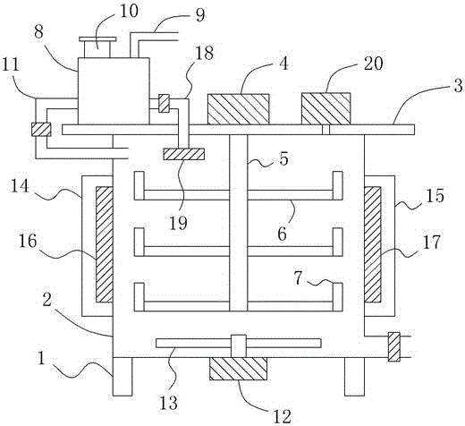
[0013] like figure 1 As shown, a new type of medical device sterilization device includes a bracket 1 and a box body 2 arranged on the bracket 1. A box cover 3 is arranged at the top of the box body 2, and a box body 2 is arranged on the front side wall of the box body 2. The box door (not shown in the figure) is sealed and matched with the body 2, and a top motor 4 is arranged on the box cover 3. The output shaft of the top motor 4 is arranged vertically downward and extends into the interior of the box body 2, and the top motor The bottom end of the output shaft of 4 is also connected with a rotating shaft 5 extending vertically downward. At the same time, a plurality of trays 6 are evenly sleeved on the rotating shaft 5, and a block extending vertically upward is also provided at the outer circumference of the tray 6. A water storage tank 8 is also provided above the box cover 3, a water inlet 9 and a dosing port 10 are respectively provided at the top of the water storage ...


PUM


Abstract

The invention relates to a novel sterilization device for medical apparatus and instruments. The sterilization device comprises a bracket, a box body and a box cover. A box door is formed in the front side wall of the box body, a top motor is arranged on the box cover, a rotary shaft is connected with the bottom end of an outlet shaft of the top motor, a plurality of trays are uniformly arranged on the rotary shaft in a sleeving mode, and stopping barrels are arranged on the external circumference of each tray. A water storage tank is arranged on the box cover, a water inlet and an agent feeding hole are formed in the top end of the water storage tank, a first water outlet is formed in the bottom of the left side of the water storage tank, and a first water outlet pipe is connected with the first water outlet and extends downward into the top end inside the box body. A bottom motor is arranged at the bottom end outside the box body, and a plurality of stirring bars are connected with the top end of an output shaft of the bottom motor. A left heating cavity and a right heating cavity are formed in the left side and the right side of the box body respectively, and a left electric heater and a right electric heater are arranged in the left heating cavity and the right heating cavity respectively. By means of the structure, the sterilization device is more convenient and efficient to use, and meanwhile the sterilization efficiency and sterilization effect of the sterilization device are greatly improved.

Description

technical field [0001] The invention relates to a novel sterilizing device for medical instruments. Background technique [0002] In the medical process, the used medical equipment must be sterilized before continuing to use, otherwise it is easy to cause some cross-infection and the occurrence of infectious diseases. Most of the current medical devices are sterilized by immersing them in a disinfectant, and then pouring out the disinfectant after soaking. However, the problem with this method is that the medical devices are only soaked relatively statically. In the disinfectant, this greatly reduces the disinfection efficiency and disinfection effect of the medical equipment. At the same time, after the disinfection is completed, the medical equipment must be wiped clean one by one before it can be used, which is time-consuming and labor-intensive. This has caused great inconvenience, thereby affecting the performance and scope of application of the disinfection device. ...

Claims


Application Information

Patent Timeline
IPC IPC(8): A61L2/18A61L2/04F26B11/18F26B23/04F26B21/00B08B3/02
CPCA61L2/04A61L2/18A61L2202/24B08B3/02F26B11/18F26B21/001F26B21/004F26B23/04
Inventor 缪家戌
Owner CHENGDU KECHUANG JIASI TECH
Learn More