A filter cartridge dust collector with uniform air supply

A filter cartridge dust collector and dust collector technology, applied in chemical instruments and methods, separation methods, and dispersed particle separation, etc., can solve the problem of uneven dust removal load of filter cartridges, uneven airflow into the filter cartridge dust collector, and low dust removal efficiency and other problems, to achieve the effect of improving the dust removal effect, uniform airflow size, and consistent dust removal load

Active Publication Date: 2018-09-14
XIAN XIKUANG ENVIRONMENTAL PROTECTION
View PDF4 Cites 0 Cited by
  • Summary
  • Abstract
  • Description
  • Claims
  • Application Information

AI Technical Summary

Problems solved by technology

[0004] Aiming at the technical problems that the air inlet airflow of the filter cartridge dust collector in the prior art is not uniform, so that the dust removal load of each filter cartridge is different, the dust removal efficiency is low, and there is no pretreatment before the wind enters the filter cartridge, so that the dust removal efficiency is low, the present invention provides The following technical solutions are solved:

Method used


Image

  • A filter cartridge dust collector with uniform air supply
  • A filter cartridge dust collector with uniform air supply
  • A filter cartridge dust collector with uniform air supply

Examples


Embodiment 1

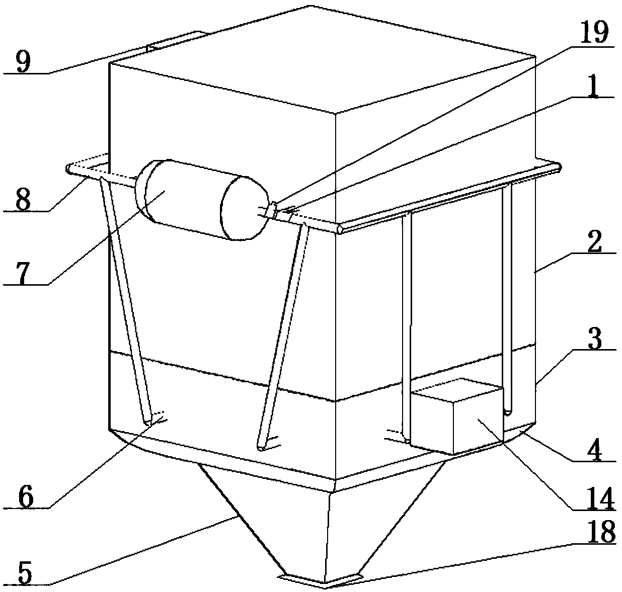
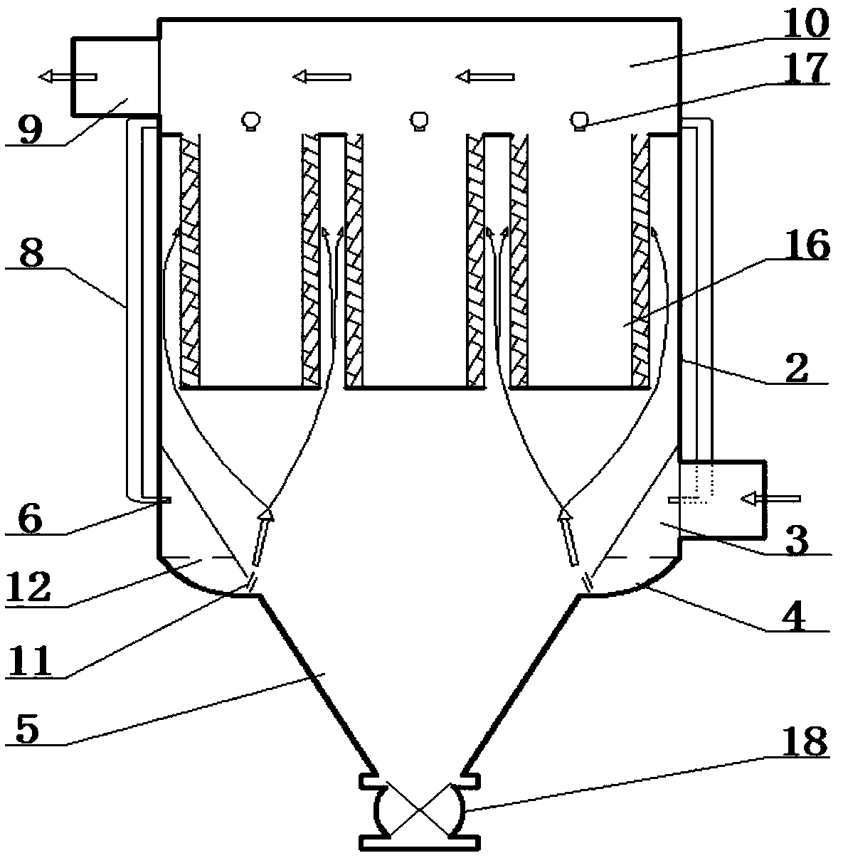
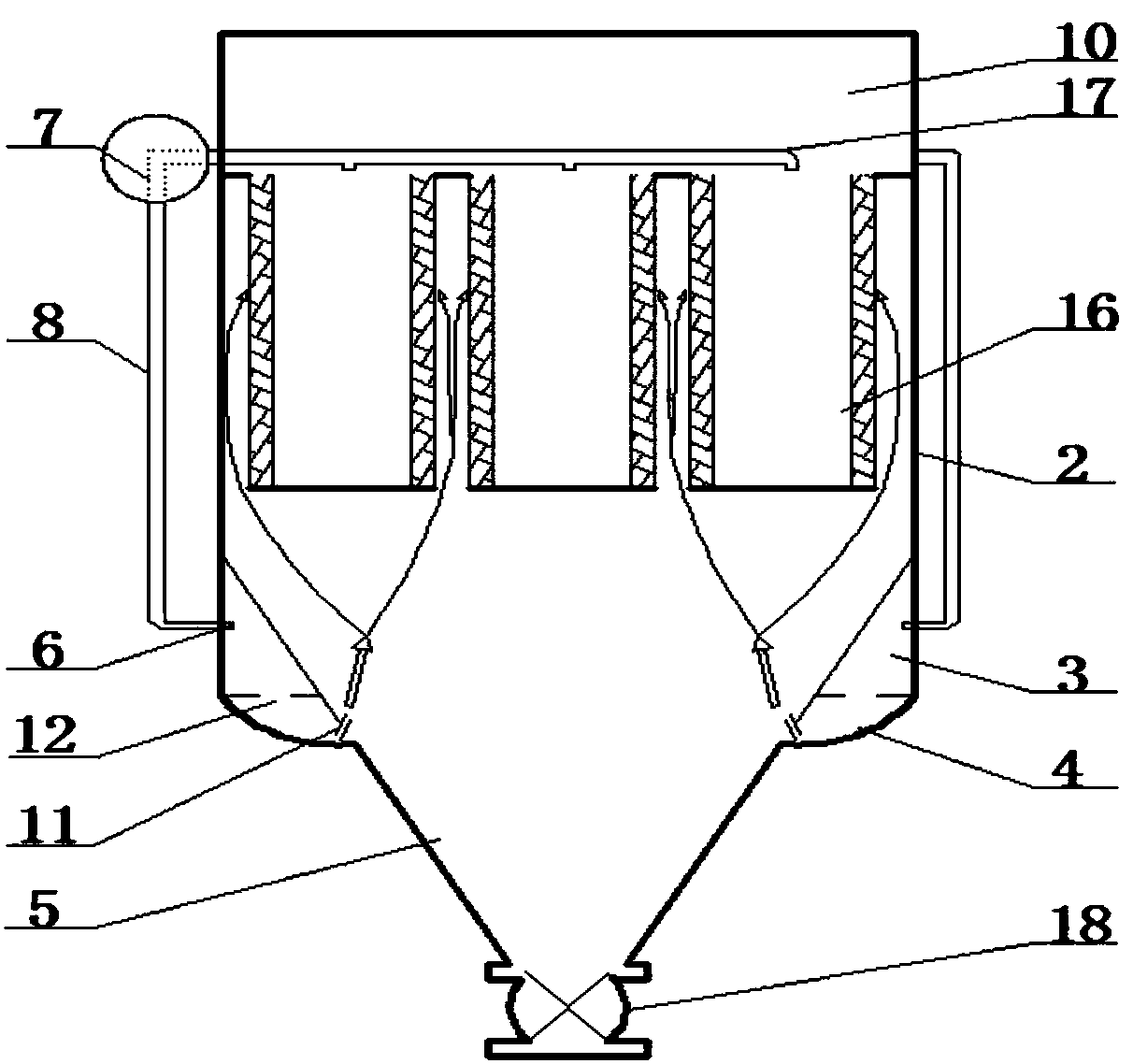
[0026] Such as Figure 1-5 , a filter cartridge dust collector with uniform air supply, including a dust collector box 2 and an ash hopper 5, the ash hopper 5 is arranged below the dust collector box 2 and communicates with it; it also includes an air supply device, and the air supply device includes an annular The air duct 3 and the annular static pressure box 4; the annular air duct 3 is set on the outer side of the upper end of the ash bucket 5 and communicated with the ash bucket 5; the annular static pressure box 4 is set on the outer side of the upper end of the ash bucket 5, and the annular static pressure box 4 The upper end surface and the lower end surface of the annular air duct 3 are attached and connected, and the two communicate through a plurality of vents 12 evenly arranged; one side of the annular air duct 3 is provided with an air inlet 14; the diameter of the plurality of vents 12 is It is satisfied that the gas flow rate of the annular air duct 3 entering t...

Embodiment 2

[0045] 1. Design and theory of circular air duct tuyere

[0046] When the air supply device of the present invention works, as Figure 4 As shown, the airflow enters the 8 air outlets on both sides of the circular air duct. In order to supply air evenly, the air volume of each air outlet is equal, and the distance between the air outlets is 0.2m. The air volume of the air duct on both sides of the air duct containing dust is approximately equal, so only one side is considered, and the air volume at the inlet end of the annular air duct is Q 0 , with a size of 2880m 3 / h Number each opening once from the end of the duct to the inlet. Area f of No. i+1 tuyere i+1 for:

[0047] f i+1 =Q 0 / nv i+1 (1)

[0048] n—the number of tuyere, n=8.

[0049] The outflow velocity of No. i+1 tuyere is:

[0050]

[0051] In the formula, μ—the flow coefficient of the air outlet, the circular side air outlet of the air duct is taken as μ=0.62;

[0052]ρ—air density, take ρ=1.2kg / m ...


PUM


Abstract

The invention discloses a filter cartridge dust collector with uniform air supply, which comprises a dust removal box body and an ash hopper, wherein the ash hopper is arranged below the dust removal box body and communicated; And the filter cartridge, the outer side wall of the upper end of the ash hopper is provided with an air duct and a static pressure box. Through the different settings of the vent area, the consistency of the air volume of each air outlet is ensured. After further equalization by the static pressure box, the air flow into the filter cartridge is uniform in size, ensuring the same dust removal load of each filter cartridge, and improving the filter cartridge. The dust removal efficiency also prolongs the service life of the filter cartridge. The airflow enters the annular pipe and the static pressure box through the air inlet, the contact area suddenly increases, the gas pressure becomes smaller, and the large particles in the air sink to the ash hopper under the action of gravity to prevent the filter cartridge from being blocked by large particles. Improve the dust removal effect.

Description

technical field [0001] The invention relates to the field of air purification treatment, in particular to a filter cartridge dust collector for uniform air supply. Background technique [0002] Most of the existing filter cartridge dust collectors directly supply air to the filter cartridge through the air inlet, which leads to uneven airflow of each filter cartridge dust collector, which makes the dust removal load of each filter cartridge in the filter cartridge dust collector different, and the dust removal efficiency is low. , and the filter cartridge is easy to wear. [0003] In addition, the existing filter cartridge dust removal method does not have pre-dust removal treatment before the wind enters the filter cartridge for filtration, so that large particles of impurities in the air are directly adsorbed on the filter cartridge, which increases the filter load and affects the dust removal effect, and requires frequent replacement of the filter cartridge. barrel, incr...

Claims


Application Information

Patent Timeline
Patent Type & Authority Patents(China)
IPC IPC(8): B01D50/00
CPCB01D50/20
Inventor 樊越胜王英志杨静王欢张鑫
Owner XIAN XIKUANG ENVIRONMENTAL PROTECTION
Why Eureka
Try Eureka