Roller type low-frequency vibrational drilling worktable

A low-frequency vibration, worktable technology, applied in the direction of manufacturing tools, metal processing, boring/drilling, etc., can solve the problems of no vibration excitation device, inability to adapt to processing occasions and conditions, difficult to change vibration processing parameters, etc. The effect of smooth processing and good promotion prospects

Active Publication Date: 2017-02-22
KEYIZHAN INTELLIGENT EQUIP CO LTD +1
View PDF8 Cites 1 Cited by
  • Summary
  • Abstract
  • Description
  • Claims
  • Application Information

AI Technical Summary

Problems solved by technology

[0004] However, the popularization and application of vibration drilling technology is not very good, the main reason is that it is difficult to change th...

Method used


Image

  • Roller type low-frequency vibrational drilling worktable
  • Roller type low-frequency vibrational drilling worktable
  • Roller type low-frequency vibrational drilling worktable

Examples


Embodiment Construction

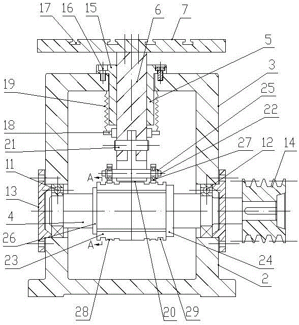
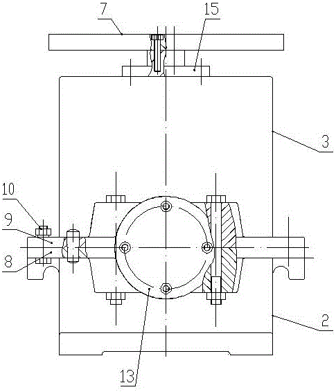
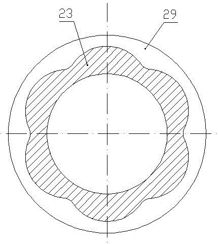
[0020] Such as figure 1 , figure 2 with image 3 As shown, the roller-type low-frequency vibration drilling table of the present invention includes a drive motor (not shown in the figure), a lower box 2, an upper box 3, a rotary drive shaft 4, a linear bearing 5, and a linear drive shaft 6 And the platen 7, the top of the lower box 2 is open, the bottom of the upper box 3 is open, the outer ring of the upper end of the lower box 2 is provided with a lower mounting ring plate 8, and the outer ring of the lower end of the upper box 3 is provided with an upper mounting ring plate 9, the upper end of the lower box body 2 is docked with the lower end of the upper box body 3 and is connected by fastening bolts 10 passing through the lower installation ring plate 8 and the upper installation ring plate 9, and the joint between the lower box body 2 and the left side of the right box body A left bearing chamber is provided, and a right bearing chamber is arranged at the junction of ...


PUM


Abstract

The invention provides a roller type low-frequency vibrational drilling worktable which comprises a driving motor, a lower box body, an upper box body, a rotary driving shaft, a linear bearing, a linear driving shaft and a table plate. The upper end of the lower box body abuts and is connected with the lower end of the upper box body by means of fastening bolts. The left end and the right end of the rotary driving shaft are respectively rotationally arranged on the left sides and the right sides of the lower box body and the upper box body. The linear bearing of which the lower end extends into the upper box body is arranged at the top of the upper box body. The linear driving shaft penetrates the linear bearing in a sliding manner. The upper end of the linear driving shaft is fixedly connected with the lower surface of the table plate. A fixed frame is arranged at the lower part of the linear driving shaft. A compression spring is arranged between the lower surface of the top of the lower box body and the fixed frame. The lower end of the linear driving shaft is in transmission connection with the rotary driving shaft through a low-frequency vibration mechanism. The roller type low-frequency vibrational drilling worktable can realize stepless adjustment of the vibration frequency, the low-frequency vibration amplitude can be adjusted, a set of available vibration and drilling parameters can be conveniently found, and processed parts can be processed.

Description

technical field [0001] The invention belongs to the technical field of mechanical processing, in particular to a roller-type low-frequency vibration drilling workbench. Background technique [0002] Holes are the basic shapes and surfaces that make up mechanical parts, and hole processing is the most common processing technology in mechanical processing. Relevant data show that: about 30% of the machining is the machining of holes, of which about 80% are processed by cutting, and the amount of metal removal in hole machining accounts for about 1 / 3 of the total amount of metal removal in machining . [0003] Deep hole processing is an important branch in the field of mechanical processing, and has a wide range of applications in defense industry, oil mining, aerospace, machine tools, automobiles and other industries. Deep hole processing is very different from turning and milling. In the process of deep hole processing, the cutting conditions of the drill bit are very harsh...

Claims


Application Information

Patent Timeline
IPC IPC(8): B23B41/02B23B47/00B23B47/02
CPCB23B41/02B23B47/00B23Q5/00
Inventor 焦锋殷森李章东童景琳卞平艳田军伟王亮亮
Owner KEYIZHAN INTELLIGENT EQUIP CO LTD
Why Eureka
Try Eureka