Welding structure and method for vacuum brazing of metal plates and metal fins

A metal fin, welding structure technology, applied in welding equipment, welding equipment, metal processing equipment and other directions, can solve the problems of unstable welding quality, large fin thickness, low connection strength, etc., to solve the problem of unstable welding quality, The effect of ensuring the spacing size and improving production efficiency

Active Publication Date: 2017-02-22
深圳市晟达真空钎焊技术有限公司
View PDF9 Cites 0 Cited by
  • Summary
  • Abstract
  • Description
  • Claims
  • Application Information

AI Technical Summary

Problems solved by technology

[0003] 1. Use the metal plate base 2a and the metal fin 1a to directly weld the metal fin and the metal base with the fixture, and the radiator products with thinner and denser fins are generally made of S-shaped metal folded fins. components, place the fins as a whole on top of the metal plate, and then weld the contact parts, such as figure 1 As shown, but the tooling fixture is complicated and there are many processes. Due to the unstable welding quality, the fins are often deformed, and the welding area between the fins and the base is small, and the connection strength is low, which may easily lead to problems such as false welding.
[0004] 2. Made in the form of shovel fins, such as figure 2 As shown, by directly processing the metal fin 1b on the metal pl

Method used


Image

  • Welding structure and method for vacuum brazing of metal plates and metal fins
  • Welding structure and method for vacuum brazing of metal plates and metal fins
  • Welding structure and method for vacuum brazing of metal plates and metal fins

Examples


Embodiment Construction

[0040] In order to have a clearer understanding of the technical features, purposes and effects of the present invention, the specific implementation manners of the present invention will now be described with reference to the accompanying drawings.

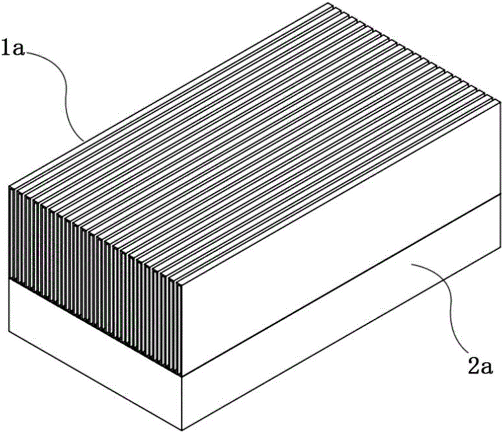
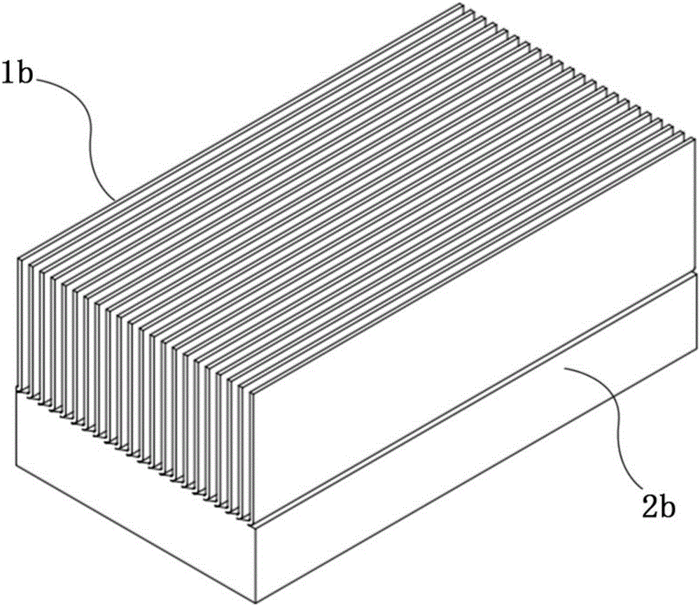
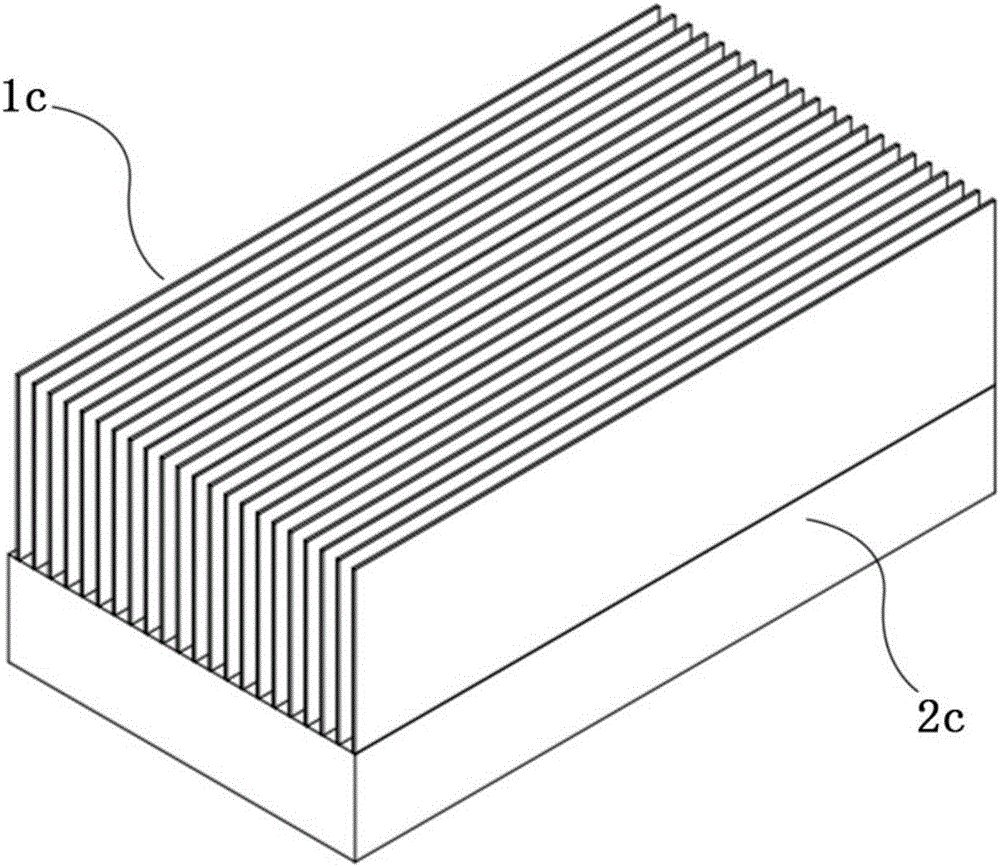
[0041] The vacuum brazing welding structure of a metal plate and a metal fin of the present invention is especially suitable for processing heat sink products with denser and thinner fins in main applications. The present invention also adopts metal fins, but the metal fins can be composed of a plurality of individual metal sheets (strengths) or integral metal folded fins, but it is different from the vacuum brazing structure of the existing radiators. Invention During the manufacturing process, the overall volume of the metal fins already includes the volume of the solid base, that is to say, the metal fins that need to be made into a solid base are interspersed with metal fins that can be connected to the adjacent metal fins by ...


PUM


Abstract

The invention discloses a welding structure for vacuum brazing of metal plates and metal fins. The welding structure comprises the metal fins, and further comprises the metal plates and solder layers as well as a welding clamp for clamping and fixing the welding main body, wherein the metal fins are formed by arranging a plurality of ribs at intervals in parallel; the solder layers are arranged at the two sides of each metal plate to form composite soldering plates; the plurality of composite soldering plates are separately inserted into intervals among the ribs to form a welding main body; thicknesses of the composite soldering plates are equal to spacing among the ribs, and height of the composite soldering plates is smaller than height of the metal fins, and length of the composite soldering plates is greater than that of the metal fins; and the welding clamp comprises a clamping structure for clamping and fixing two side surfaces, parallel to the composite soldering plates, of the welding main body. The invention further discloses a welding method for vacuum brazing of metal plates and the metal fins. According to the welding structure and the welding method disclosed by the invention, the metal plates and the metal fins are delicately designed in a matched mode, so that finished products subjected to vacuum welding can obtain better welding quality, and therefore, production efficiency is improved and production cost is reduced.

Description

technical field [0001] The invention relates to a welding structure, in particular to a welding structure and method for vacuum brazing of a metal plate and a metal fin, which can avoid the problem of virtual welding between the metal fin and the metal base. Background technique [0002] Nowadays, in the case of increasing precision and quality requirements in the metal processing industry, in the field of welding processing, the demand for high quality welding is also increasing. Vacuum brazing means that the workpiece is heated in a vacuum chamber, and it is mainly used for welding of high-quality products and easily oxidized materials. It can achieve a more precise and perfect welding effect than ordinary welding, and meet the welding needs of more precise metal devices. For example, the processing of the metal structure part of the heat sink that is very commonly used in the market; in order to make the heat dissipation effect better, the heat sink generally includes a ...

Claims


Application Information

Patent Timeline
IPC IPC(8): B23K3/08B23K1/008B23K31/02B23K33/00
CPCB23K1/008B23K3/087B23K31/02B23K33/00
Inventor 陈基明
Owner 深圳市晟达真空钎焊技术有限公司
Why Eureka
Try Eureka