
a rolling head

A rolling head and rolling technology, applied in the field of rolling head, can solve problems such as difficulty in meeting processing requirements at one time, unqualified parts assembly, low production efficiency, etc.

Active Publication Date: 2018-12-04
SHAANXI UNIV OF SCI & TECH
View PDF7 Cites 0 Cited by
  • Summary
  • Abstract
  • Description
  • Claims
  • Application Information

AI Technical Summary

Problems solved by technology

[0002] The rolling head in the existing factory workshop is still implemented by simple and rough separate rolling and partial manual beating, which leads to the investment of too much equipment on the production line, and the production efficiency is low. In addition, separate rolling leads to increased errors in repeated positioning , leading to an increase in the error of the final workpiece processing, it is difficult to meet the processing requirements at one time
The above problems are problems that cannot be solved by rolling in current drying equipment, especially the surface of the workpiece is curved, it is difficult to effectively roll in place, resulting in unqualified assembly of parts

Method used


Image

  • a rolling head
  • a rolling head
  • a rolling head

Examples


Embodiment Construction

[0027] The present invention will be described in further detail below in conjunction with the accompanying drawings.

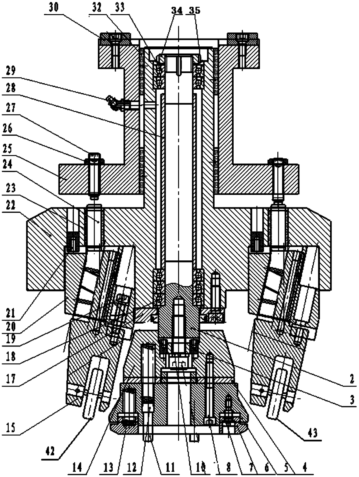
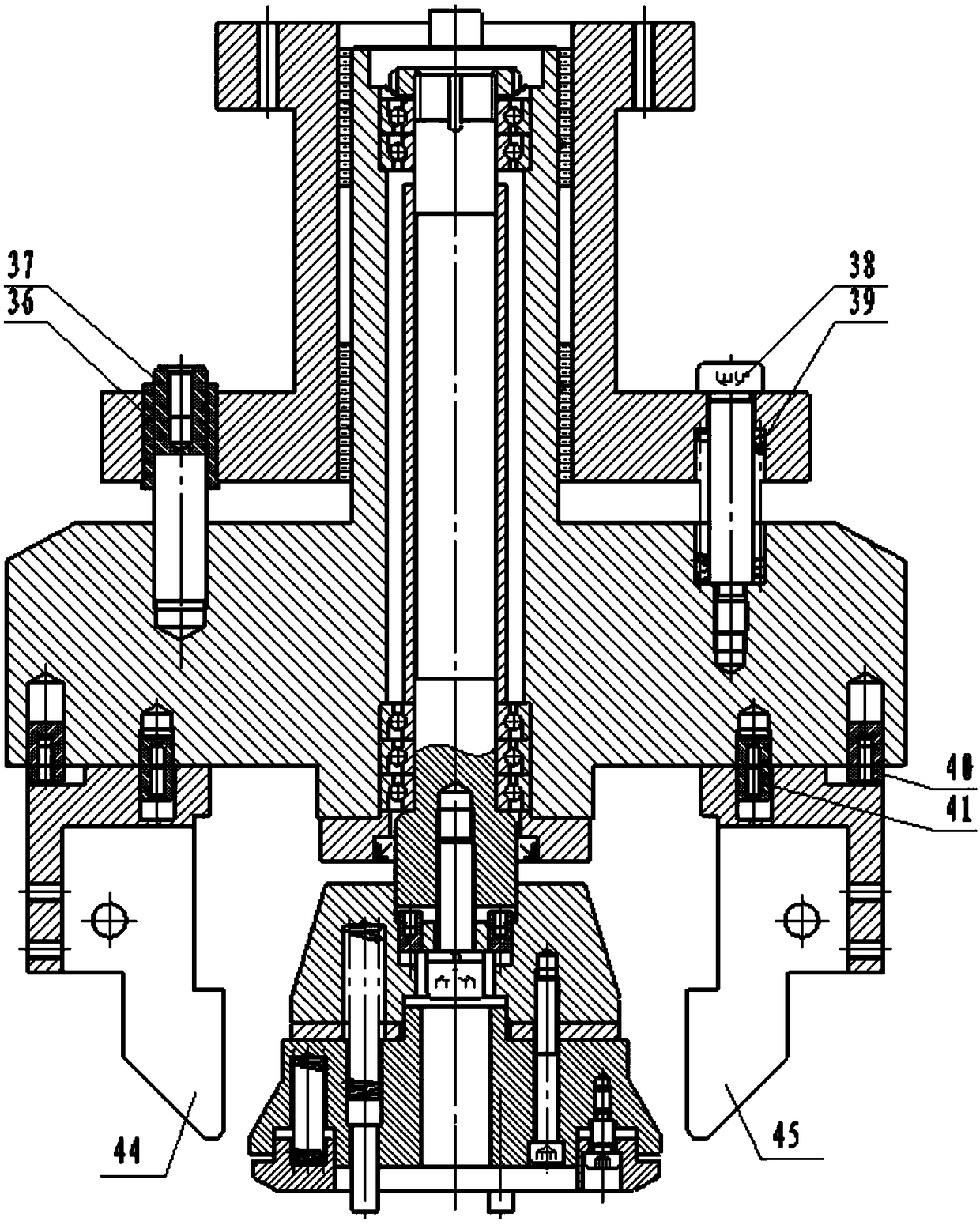
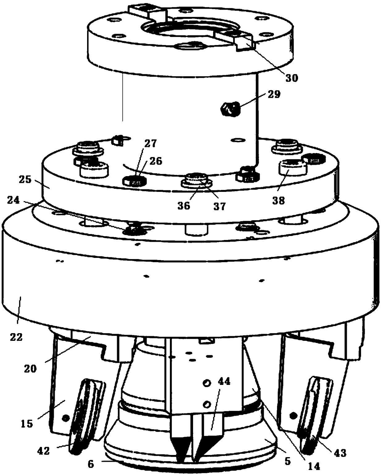
[0028] see figure 1 and image 3 Shown:

[0029] Compression part: Three hexagon socket head cap screws arranged in the circumferential direction fix the triangular pad 17 on the rolling lower body 22 to ensure that the three angular contact ball bearings 18 do not fall off, and at the same time block the central shaft 2 so as not to loosen. Two square round keys 2 3 are installed in the large end slot of the central shaft 2, and the lower end is stuck in the two holes of the pressing disc seat 14, then screw on the hexagon socket head cap screw and add the spring washer 10 to make the center The shaft 2 and the compression disc seat 14 can not move relative to each other in the circumferential direction and the axial direction, so that it can be lowered accurately; The position between the workpieces is convenient for turning down and rolling in the next ...


PUM


Abstract

The invention discloses a novel rolling head. The novel rolling head comprises a pressing part, a toppling part, a rolling part and a pressure applying part. The technical scheme is that when the device starts operating, a motor rotates to drive a spindle to rotate, the rolling head is lowered, cylindrical pins are in contact with the surface of a workpiece firstly, a rolling upper body compresses compression springs IV, a rolling lower body, an angular contact bearing, a central shaft, square-round keys and a pressing disc seat are sequentially pressed till compression springs I are slowly compressed, toppling devices are toppled, and first-step toppling operation is achieved; the rolling head continuously rotates and declines, set screws pressing an inner roller foot are pushed to move downwards and rotate while rolling, an outer roller is in contact with a curved surface of the workpiece and performs rotary rolling, integral rolling action is achieved, and the toppling devices are positioned on the upper side of the lower end of the roller at the moment; and after rolling, a spindle box drives the rolling head to rise to a certain height, the compression springs IV bounce off the rolling upper body and the rolling lower body, the springs at other parts recover to the previous state, and rolling operation of next workpiece is facilitated. The novel rolling head has the characteristics that the time and space are saved, and the production efficiency is improved.

Description

technical field [0001] The invention relates to the technical field of rolling heads, in particular to a rolling head. Background technique [0002] The rolling head in the existing factory workshop is still implemented by simple and rough separate rolling and partial manual beating, resulting in too much equipment being invested in the production line, and the production efficiency is low. In addition, separate rolling leads to increased errors in repeated positioning , leading to an increase in the error of the final workpiece processing, it is difficult to meet the processing requirements at one time. The above problems are problems that cannot be solved by rolling in current drying equipment, especially the surface of the workpiece is curved, so it is difficult to effectively roll in place, resulting in unqualified assembly of parts. Contents of the invention [0003] In order to overcome the deficiencies of the above-mentioned prior art, the object of the present inv...

Claims


Application Information

Patent Timeline
Patent Type & Authority Patents(China)
IPC IPC(8): B23P9/02
CPCB23P9/02
Inventor 任工昌杨宇龙张文静高谨徐洋洋宜永刚刘崇展景遍
Owner SHAANXI UNIV OF SCI & TECH
Learn More