Automatic threading mechanism

A technology for automatic threading and transmission components, applied in metal processing, metal processing equipment, manufacturing tools, etc., can solve the problems of unstable quality, low intubation efficiency, affecting intubation efficiency, etc., to achieve a wide range of applications and improve intubation. The effect of efficiency

Inactive Publication Date: 2017-02-22
LIANWEICHUANG SCI & TECH TIANJIN
View PDF7 Cites 0 Cited by
  • Summary
  • Abstract
  • Description
  • Claims
  • Application Information

AI Technical Summary

Problems solved by technology

When the U-shaped tube passes through the stacked fins, it is difficult to ensure that the copper tube can pass through all the fins in sequence, and due to the difference in the magnitude of the artificial force, the shaking and offset of the copper tube cannot be avoided, and the intubation process is often Defects such as fin group deformation, U-shaped tube breakage, skewing, and jamming occur, so higher requirements are placed on the coordination of human operations
Manual intubation has many problems such as low intubation efficiency, unstable quality, high scrap rate, high technical requirements for personnel, and high labor costs.
[0004] In the prior art, there is an automatic intubation device that can fully automatically intubate the U-shaped tubes of the condenser fins. Since the length of the U-shaped tubes is not single, and the length is very long, the U-shaped tubes will be transported during use. Slippage, cannot be fixed on the intubation machine through the U-shaped tube at one time, and the intubation machine for the U-shaped tube that is too long cannot ensure that the U-shaped tube is always kept in a vertical state during transportation. These problems will affect the intubation efficiency

Method used


Image

  • Automatic threading mechanism
  • Automatic threading mechanism
  • Automatic threading mechanism

Examples


Embodiment Construction

[0029] Specific embodiments of the present invention will be described in detail below in conjunction with the accompanying drawings.

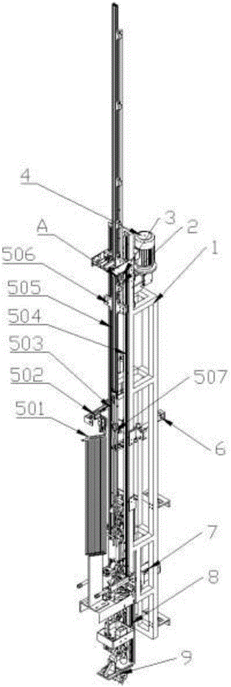
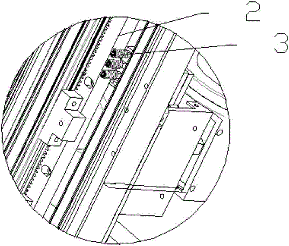
[0030] Such as Figure 1-Figure 5 As shown, the present invention provides an automatic film threading mechanism, including an intubation frame 1, which is provided with a U-shaped tube feeding and pushing device 5, a guiding transmission device 8, and an insertion and positioning device 9. The U-shaped tube supply and pushing device 5 includes a tube supply assembly and a push tube assembly. The tube assembly is pushed to the insertion and positioning device 9 via the guide transmission device 8, a rack assembly 2 is provided on one side of the push tube assembly, and a rack stopper 3 is provided on one side of the rack assembly 2 , the rack stopper 3 is fixed on the intubation holder 1;

[0031] The push tube assembly includes a push plate 506, a push frame 505, a first slide rail 504 and a clamping device 503, the push plate 506 is fixed ...


PUM


Abstract

The invention provides an automatic threading mechanism. The automatic threading mechanism comprises a pipe inserting frame, wherein a U-shaped pipe supplying and pushing device, a guide driving device and an inserting and positioning device are arranged on the pipe inserting frame; the U-shaped pipe supplying and pushing device comprises a pipe supplying component and a pipe pushing component; the pipe pushing component is connected with a driving motor; the pipe supplying component conveys a U-shaped pipe to the pipe pushing component; the U-shaped pipe is pushed to the inserting and positioning device by the pipe pushing component via the guide driving device; a rack component is arranged at one side of a push frame; a rack stopping frame is arranged at one side of the rack component and is fixed on the pipe inserting frame; a fixing component which can be used for clasping the U-shaped pipe is arranged at the lower end of the pipe pushing component; and the guide driving device comprises a fixed guide driving component, a movable guide driving component positioned below the guide driving device and a limiting shaft positioned between the two components. The automatic threading mechanism provided by the invention has the advantages that the automation degree of equipment is high, the safety and the reliability in use are realized, the production efficiency and the accuracy of pipe inserting are improved, and the production cost is reduced.

Description

technical field [0001] The invention belongs to the technical field of condenser fin automatic intubation, and in particular relates to an automatic sheet threading mechanism. Background technique [0002] The production of heat exchangers in many industries (such as the air-conditioning industry) includes the intubation process. Taking the air-conditioning condenser as an example, the air-conditioning condenser is assembled through U-shaped tubes and fins, end plates and fins, and U-shaped. The assembly of elbows and U-shaped tubes, and the 90-degree bending of fin groups are processed and formed. Inserting U-shaped tubes on the condenser fins has become an important link in the preparation of air conditioners. [0003] At present, the intubation of U-shaped tubes of condenser fins in China is basically realized by manual work. It grabs the copper tubes manually or by a robot, and then manually inserts the U-shaped copper tubes one by one into the fin channel formed by ali...

Claims


Application Information

Patent Timeline
Patent Type & Authority Applications(China)
IPC IPC(8): B23P19/00
CPCB23P19/00B23P19/001
Inventor 张俊华严家保孟广朋
Owner LIANWEICHUANG SCI & TECH TIANJIN
Why Eureka
Try Eureka