Double-clip force multiplying type jaw vice structure

A double-clamp multi-force type, vise technology, applied in the field of vise structure, can solve the problems of insufficient clamping force of the workpiece, tool vibration, difficult for users to assemble and maintain, etc.

Inactive Publication Date: 2017-02-22
HOMGE MACHINERY IND
View PDF7 Cites 1 Cited by
  • Summary
  • Abstract
  • Description
  • Claims
  • Application Information

AI Technical Summary

Problems solved by technology

[0002] The conventional double-clamp vise structure is not designed with a structural double force device. Therefore, when clamping two workpieces at the same time, not only the force of clamping the workpiece is insufficient, but also the problem of tool vibration or workpiece flying out is likely to be caused during processing. , and may even lead to the safety issue of the workpiece being thrown out and hurting the operator
[0003] Facing the above-mentioned problems of the traditional double-clamp vise, some people further develop the hydraulic double-clamp vise. Although a pressurized structure is installed to increase the clamping force, it can avoid the problem of poor clamping force of the traditional vise. , but the hydraulic vise has many parts and components, not only the overall production cost is high, but also it is not easy for users to assemble and maintain. What's more, the hydraulic vise is likely to cause oil leakage, which indirectly affects other Clamping strength, therefore, it is necessary to further improve it in view of the various deficiencies known to all

Method used


Image

  • Double-clip force multiplying type jaw vice structure
  • Double-clip force multiplying type jaw vice structure
  • Double-clip force multiplying type jaw vice structure

Examples


Embodiment Construction

[0069] In order to further explain the technical solution of the present invention, the present invention will be described in detail below through specific examples.

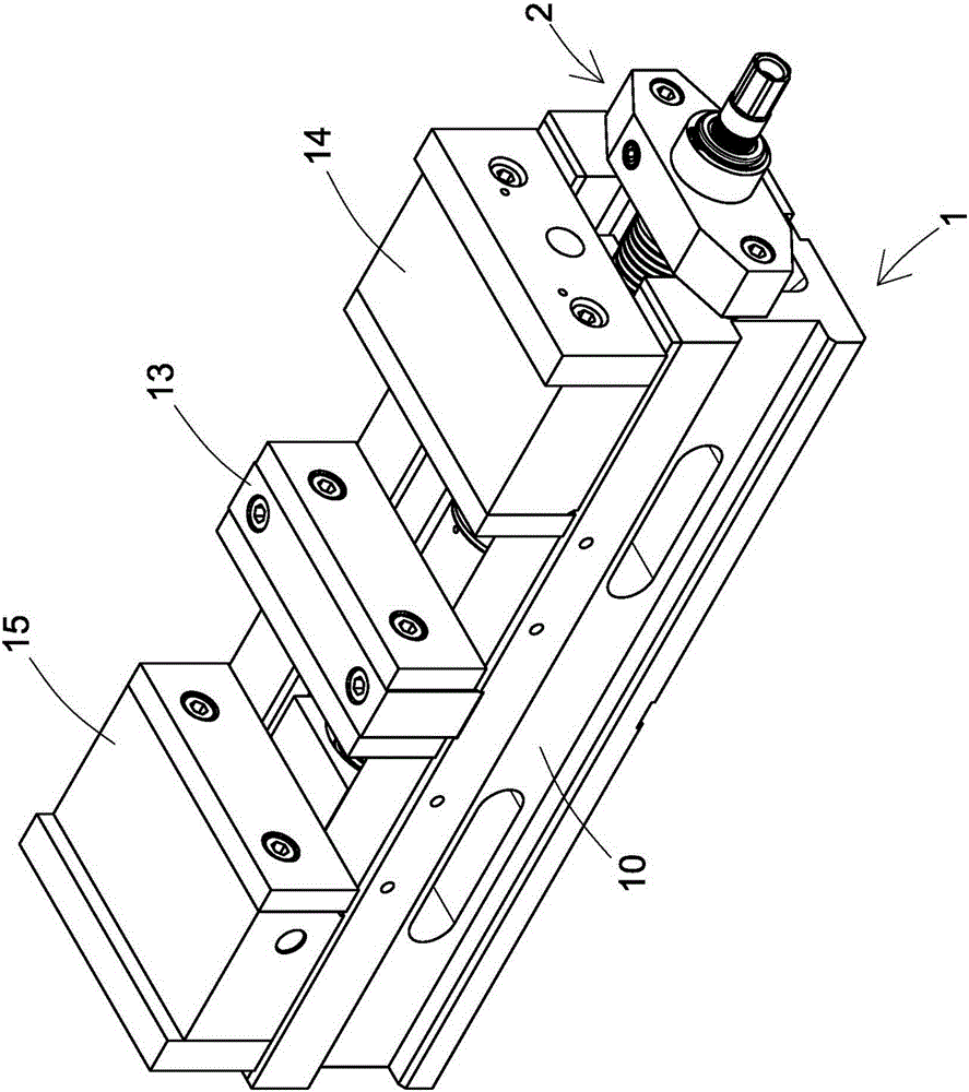
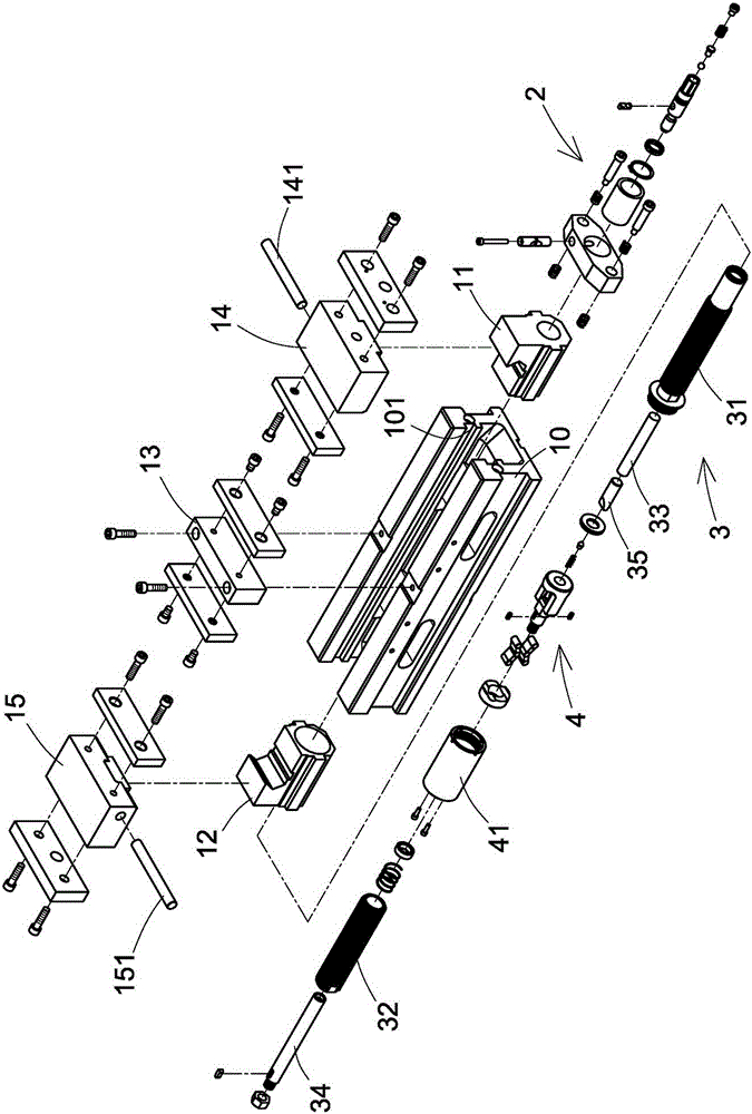
[0070] First, please refer to Figure 1 to Figure 6 Shown, the present invention is a kind of double-clamp multiplier type vise, and it comprises:

[0071] A vise unit 1, the vise unit 1 has a body 10, the body 10 is provided with a sliding groove, the opposite sides of the inner edge of the sliding groove are respectively provided with a guide rail 101, and the two guide rails 101 respectively provide a The anterior angle tooth base 11 of the inclined surface 111 and the rear angle tooth base 12 with the second pressing inclined surface 121 are slidably set, and a fixed jaw 13 is fixed at the center of the top surface of the body 10, and the top surface of the body 10 is located at the A first movable jaw 14 with a first pressure rod 141 and a second movable jaw 15 with a second pressure rod 151 are respectiv...


PUM


Abstract

The invention discloses a double-clip force multiplying type jaw vice. The jaw vice comprises a jaw vice unit, a drive unit, a transmission unit and a force multiplying unit; a jaw vice unit body is provided with a front angle tooth base and a rear angle tooth base in a sliding manner, a fixed jaw is fixedly arranged in the center of the top face of the jaw vice unit body, a first movable jaw and a second movable jaw are arranged on the top face of the jaw vice unit body, the drive unit is arranged on the side, located on the front angle tooth base, of the body, the transmission unit is composed of a first guide screw rod, a second guide screw rod, a push rod and a pull rod, the first guide screw rod penetrates the drive unit, the second guide screw rod and the rear angle tooth base are in screwed combination, the push rod penetrates the first guide screw rod, and is pushed and abutted by the drive unit, the pull rod is arranged in the second guide screw rod in a penetrating manner, and the force multiplying unit is arranged between the first guide screw rod and the second guide screw rod and is located below the fixed jaw; therefore, two workpieces can be really and firmly clamped at the same time, the opening distance can be increased, meanwhile, the force multiplying pressurizing and clamping effect can be achieved, the number of parts is small, and a user can conveniently carry out assembling and maintaining.

Description

technical field [0001] The invention relates to a vise structure, in particular to a double-clamp type vise structure with double-force pressurized clamping effect. Background technique [0002] The conventional double-clamp vise structure is not designed with a structural double force device. Therefore, when clamping two workpieces at the same time, not only the force of clamping the workpiece is insufficient, but also the problem of tool vibration or workpiece flying out and damage is likely to occur during processing. , It may even lead to safety issues that the workpiece is thrown out and the operator is injured. [0003] Facing the above-mentioned problems of the traditional double-clamp vise, some people further develop the hydraulic double-clamp vise. Although a pressurized structure is installed to increase the clamping force, it can avoid the problem of poor clamping force of the traditional vise. , but the hydraulic vise has many parts and components, not only the...

Claims


Application Information

Patent Timeline
Patent Type & Authority Applications(China)
IPC IPC(8): B25B1/02B25B1/10
CPCB25B1/02B25B1/106
Inventor 林溪水
Owner HOMGE MACHINERY IND
Why Eureka
Try Eureka