Hydraulic manipulator

A manipulator, hydraulic technology, applied in the field of manipulators

Inactive Publication Date: 2017-02-22
ZHUHAI HENGQIN QI XIANG TECH CO LTD
View PDF7 Cites 7 Cited by
  • Summary
  • Abstract
  • Description
  • Claims
  • Application Information

AI Technical Summary

Problems solved by technology

Although this patent is also a hydraulic manipulator, it still needs to be equipped with an oil tank, an oil pump and a control system

Method used


Image

  • Hydraulic manipulator
  • Hydraulic manipulator
  • Hydraulic manipulator

Examples


Embodiment 2

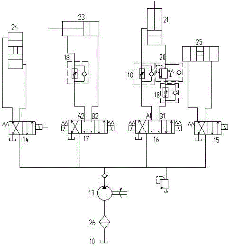
[0024]Embodiment 2: When the second three-position four-way electromagnetic reversing valve 17 is reversing to the left position, the first one-way valve inside the one-way throttle valve 18 and the adjustable throttle valve quickly feed the rodless cavity of the boom cylinder 23 quickly. Filled with oil, when the rod cavity of the boom cylinder 23 is completely filled with oil, the boom 5 rises to the highest position; when the second three-position four-way electromagnetic reversing valve 17 switches to the middle position, the first one-way valve is closed, The boom 5 is kept at the highest position, which can prevent the hydraulic manipulator from "nodding"; when the second, three-position, four-way electromagnetic reversing valve 17 is in the right position, the boom cylinder 23 has no rod cavity filled with oil, and the boom cylinder 23 has a rod The chamber pressure returns to the oil through the adjustable throttle valve. At this time, the one-way throttle valve 18 is c...

Embodiment 3

[0025] Embodiment 3: The operation mode of the two one-way throttle valves 18 connected to the first three-position four-way electromagnetic reversing valve 16 is the same as that of Embodiment 2. When the pressure in the rodless chamber of the forearm cylinder 21 reaches 1 MPa, the sequence valve will be sequenced. The valve moves to the right, and connects the oil circuit between the rodless chamber of the forearm oil cylinder 21 and the one-way throttle valve 18. At the same time, the spring chamber of the sequence valve is connected to the oil tank 10, which can ensure that the spring chamber of the sequence valve is always in a low-pressure state and prevent the sequence valve from being stuck. Simultaneously when the rodless cavity of the arm oil cylinder 21 is in a state where the pressure is lower than 1 MPa, the sequence valve closes the oil circuit between the rodless cavity of the arm cylinder 21 and the one-way throttle valve 18, and the first one-way sequence valve...


PUM


Abstract

The invention discloses a hydraulic manipulator comprising a tank body; a rotating boss and an oil filling port are formed in the tank body; the rotating boss is provided with a mounting part connected with a big arm through a mounting shaft; the big arm is hinged with one end of a forearm and is fixedly provided with a big arm cylinder; and the other end of the forearm is hinged with a gripper. When being used, the hydraulic manipulator can be mounted in a required place, and a required action is set through an operation panel as required and is stored. When the hydraulic manipulator is used, only a power supply is needed to be started every time, and a set action command is selected to operate; the inner side of each of two claws is provided with two cushion blocks, so that the grasping force of the gripper can be effectively increased; and an oil tank, a motor, a gear pump and an electric control mounting region are arranged inside the tank body, so that the structure of the hydraulic manipulator is simplified, and meanwhile, the hydraulic manipulator has the characteristic of simple appearance.

Description

technical field [0001] The invention relates to the technical field of manipulators, in particular to a hydraulic manipulator. Background technique [0002] Hydraulic transmission is a transmission method that uses liquid as the working medium to transmit energy and control. Hydraulic pressure and air pressure are collectively referred to as fluid transmission. Compared with air pressure, hydraulic transmission has the characteristics of stable transmission, small size, light weight and low inertia, so it is widely used. Applied to various machines, most of the manipulators on the market are controlled by air pressure, which has the characteristics of small torque, and the structure of hydraulic manipulators is relatively complicated. [0003] Retrieve related technologies: Chinese Patent No. 201510492851.7 discloses a hydraulic manipulator, including a base, a bracket arranged on the top of the base, a mechanical arm assembly connected to the bracket, and a clamping mechani...

Claims


Application Information

Patent Timeline
Patent Type & Authority Applications(China)
IPC IPC(8): B25J9/14B25J9/00
CPCB25J9/14B25J9/00B25J9/146
Inventor 朱璇
Owner ZHUHAI HENGQIN QI XIANG TECH CO LTD
Why Eureka
Try Eureka