Rotary assembly robot gripper

A robot gripper and frame technology, applied in the direction of manipulators, program-controlled manipulators, chucks, etc., can solve the problems of unsatisfactory multi-function, poor versatility, and small adaptability, etc., achieve compact structure, reduce labor intensity, and improve production efficiency Effect

Inactive Publication Date: 2017-02-22
YTO LUOYANG WIT TOOLS & EQUIP
View PDF11 Cites 12 Cited by
  • Summary
  • Abstract
  • Description
  • Claims
  • Application Information

AI Technical Summary

Problems solved by technology

However, most of the current robot grippers only have a single clamping function, and it is difficult to control the precise rotation angle and speed

Method used


Image

  • Rotary assembly robot gripper
  • Rotary assembly robot gripper
  • Rotary assembly robot gripper

Examples


Embodiment Construction

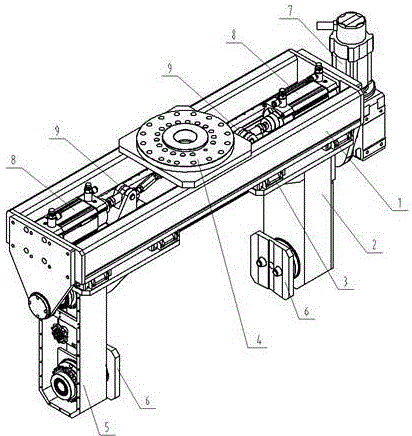
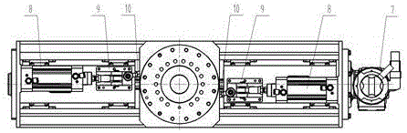
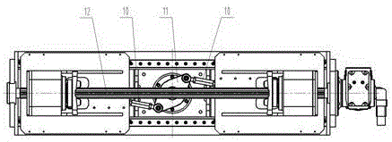
[0015] The present invention will be further described below in conjunction with the accompanying drawings. As shown in Figures 1 to 3, a rotary combined robot gripper includes: frame 1, left gripper arm 2, linear guide rail 3, connecting plate 4, right gripper arm 5, gripper 6, servo motor 7, cylinder 8 , hinge seat 9, connecting rod 10, synchronous rotation mechanism 11, and ball spline 12; among them, the connecting plate 4 is installed on the frame 1 to connect with the robot arm, and a pair of parallel linear guide rails 3 are fixed on the frame 1. The arm 2 and the right grabbing arm 5 are equipped with a chain transmission mechanism, and any structure in the prior art can be used, and will not be repeated here. The left grabbing arm 2 and the right grabbing arm 5 are symmetrically installed on the left and right sides of the linear guide rail 3. Can slide along the linear guide 3.

[0016] A hinge seat 9 is fixed on the left grabbing arm 2 and the right grabbing arm 5,...


PUM


Abstract

A rotary assembly robot gripper comprises a frame, a left gripper arm, linear guide rails, a connecting plate, a right gripper arm, gripper bodies, a servo motor, cylinders, hinge pedestals, connecting rods, a synchronous rotation mechanism and a ball spline. The connecting plate is mounted on the frame. A pair of parallel linear guide rails is fixed on the frame. The left gripper arm and the right gripper arm are symmetrically mounted on the left and the right of the linear guide rails. Cylinder block ends of the two cylinders are fixed at the left end and the right end of the frame. Ends of the two connecting rods with the same length are respectively hinged to the hinge pedestals mounted on the left gripper arm and the right gripper arm. The other ends of the connecting rods are hinged to the synchronous rotation mechanism mounted on the frame. The rotary assembly robot gripper is compact in structure and integrates multiple functions, the operation precision is remarkably superior to the manual operation precision, the production cost is reduced, the production efficiency can be remarkably improved, and the labor intensity is reduced.

Description

technical field [0001] The invention belongs to the technical field of automatic production lines, and relates to a robot gripper, in particular to a rotary combined robot gripper. Background technique [0002] With the gradual decline of the demographic dividend and the rising labor costs of enterprises, industrial robots are gradually entering the public's field of vision, and their application scope is becoming wider and wider. In the application of industrial robots, robot grippers are essential, and different grippers are required for different gripping tasks. [0003] At present, in the domestic engine cylinder body core production line, the finished sand core is usually clamped by a clamp suspended on the lifting equipment, transported to the dipping tank for dipping paint, and after repeated swinging and draining, it is placed in the Drying furnace roller table. In this process, it can only rely on manual visual inspection, and manual hand support is required to en...

Claims


Application Information

Patent Timeline
IPC IPC(8): B25J15/08B25J9/12
CPCB25J15/08B25J9/12
Inventor 潘高峰马静一徐爱丽
Owner YTO LUOYANG WIT TOOLS & EQUIP
Why Eureka
Try Eureka