Corner cutting and forming device for packaging bags

A technology of forming device and packaging bag, applied in the directions of packaging, transportation and packaging, bag making, etc., can solve the problems of easy scratching or hooking of foreign objects, unsightly appearance, puncture damage to the outer packaging, etc., and shorten the cutting time. , easy to separate, reduce the effect of cutting force

Active Publication Date: 2019-01-25
珠海瑞创科技发展有限公司
View PDF7 Cites 2 Cited by
  • Summary
  • Abstract
  • Description
  • Claims
  • Application Information

AI Technical Summary

Problems solved by technology

[0002] With the improvement of people's living standards, there are more and more types of packaging bags for packaging food, medicine, medical products, groceries and other items. Therefore, the packaging of various foods or groceries is becoming more and more diverse. The packaging bag is square or long. The four corners of this kind of packaging bag have sharp corners, which is not only not beautiful in appearance, but also for these packaging bags made of hard materials, the sharp corners are very sharp and thorny. Bad outer packaging, easy to scratch or catch other foreign objects, and even cause danger, especially some packaging involving children

Method used


Image

  • Corner cutting and forming device for packaging bags
  • Corner cutting and forming device for packaging bags
  • Corner cutting and forming device for packaging bags

Examples


Embodiment 1

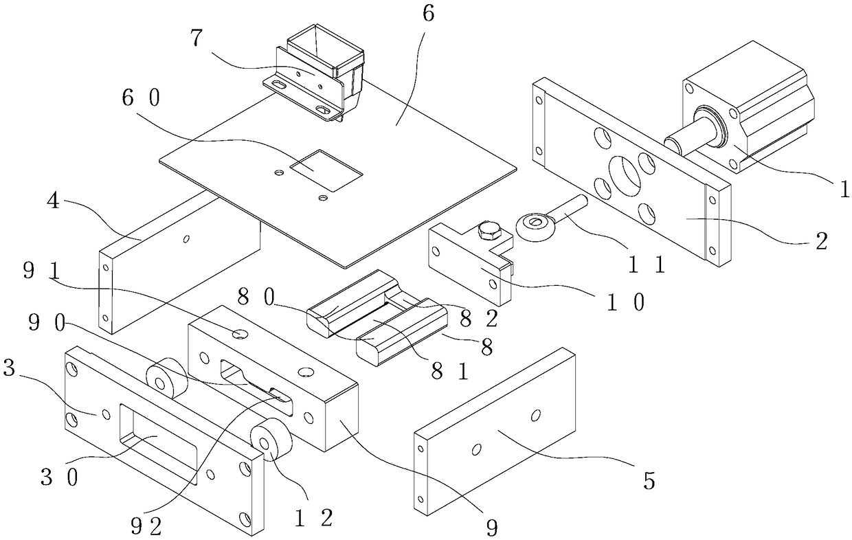
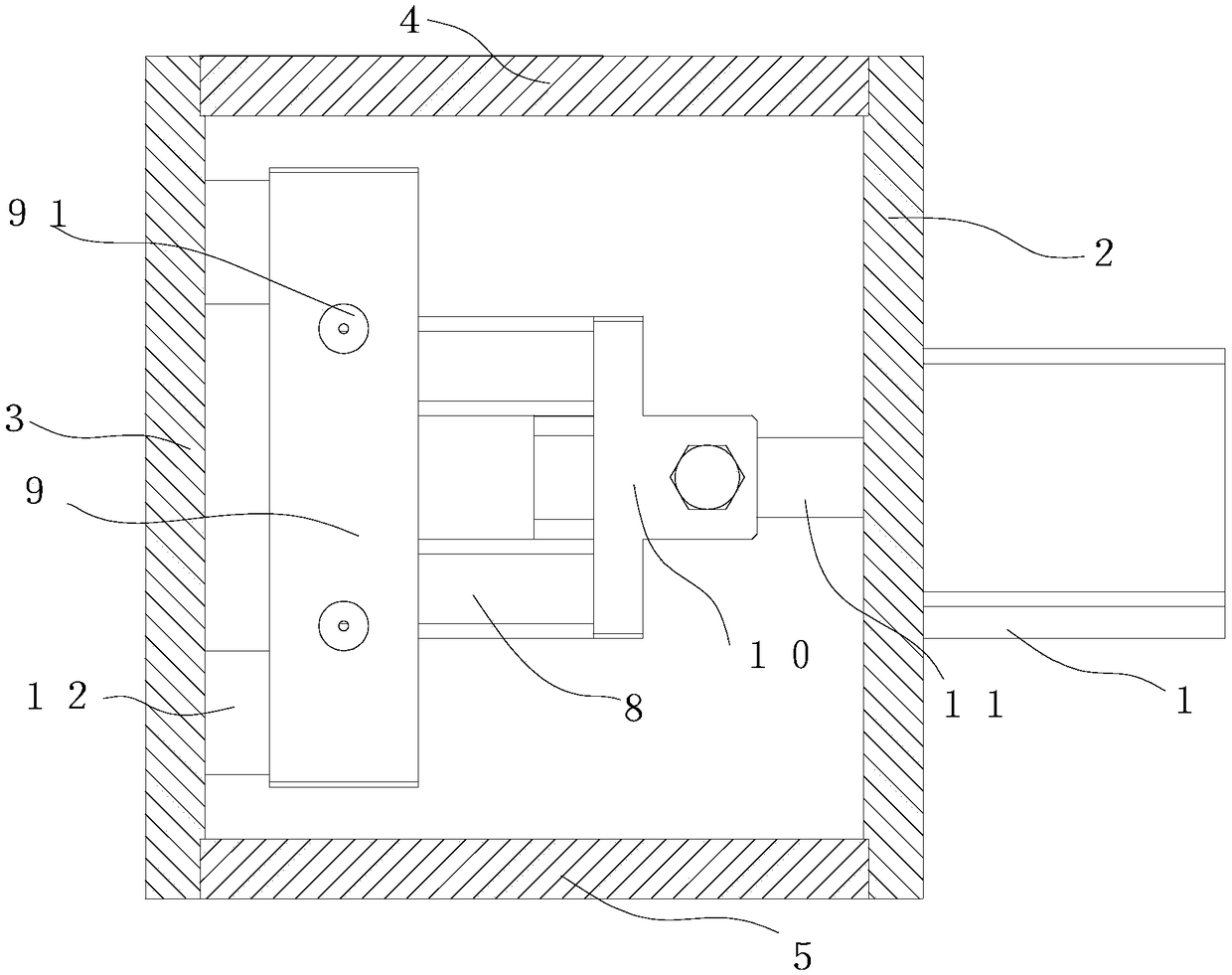
[0051] Corner cutting and forming devices for packaging bags, such as Figure 1 to Figure 5 As shown, it includes a drive unit 1, a fixed frame and a belt guide bucket 7 that facilitates the sequential streamline introduction of the one-piece packaging bag X after filling. The fixed frame consists of a front horizontal plate 2, a rear horizontal plate 3, a left The plate 5 and the knife box cover 6 are composed, and the ends of the front horizontal plate 2, the right side plate 5, the rear horizontal plate 3 and the left side plate 4 are sequentially fixed into one body through screw connection, and the driving unit 1 is a pneumatically driven cylinder. The drive unit 1 is installed on the outer wall of the front side of the front cross plate 2, and the knife box cover 6 is installed and fixed on the upper side of the integrally connected front cross plate 2, right side plate 5, rear cross plate 3 and left side plate 4, and the knife box cover 6 A material guide port 60 is pro...

Embodiment 2

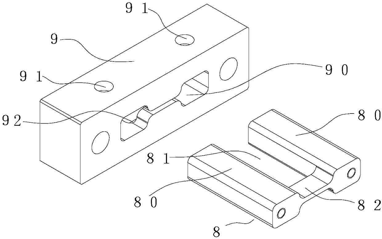
[0058] like Image 6 and Figure 7 As shown, the difference between this embodiment and Embodiment 1 is that the front side of the guide groove 81 of the front cutter 8 corresponds to the I-shaped convex edge 82 from the passage of the one-piece packaging bag to be punched corresponding to the rear cutter. The two sides of the guide groove 81 form a guide angle α that shrinks inwardly to prevent the jamming of the one-piece packaging bag and the angle of the punching fillet. The angle of the guide angle α is 16°, and the guide angle α is in the column shape The inner side of the guide rail 80 forms two center-symmetric guide surfaces 800 with the same inclination angle. Compared with the guide angle of 16°, the inclination angle of the guide surface 800 is 8°. The distance converging on both sides of the I-shaped convex edge 82 is consistent with the width of the one-piece packaging bag to be blanked.

[0059] In this way, the guide angle α contracting inward is formed by th...

Embodiment 3

[0061] like Figure 8 to Figure 11 As shown, the difference between this embodiment and the second embodiment is that the shearing surface of the rear cutter 9 also forms a symmetrical distribution on the left and right, and the cone protrudes in the direction of the I-shaped convex edge 82 of the forward cutter 8 to facilitate shearing. The packaging bag and the cutting lobe β that separates from the waste material have an angle of 174°.

[0062] The rear cutter is designed with a tapered protrusion to facilitate the cutting of the one-piece packaging bag and the cutting lobe β that is separated from the waste. When cutting, the rear cutter 9 forms a cutting that first pierces through the middle and then cuts to both sides. The force on the cutting edge is uniform, the cutting force is reduced, and the cutting time is shortened, so that the cutting is smooth, and the incision of the cut out packaging bag is smooth, and after increasing the cutting lobes, the contact surface b...


PUM


Abstract

The invention provides a corner cutting forming device for packaging bags. The corner cutting forming device comprises a driving unit, a fixed frame and a belt guide hopper. The belt guide hopper is used for guiding packed one-piece packaging bags along an assembly line in sequence. The driving unit is mounted on the outer wall of the front side of the fixed frame. The belt guide hopper is mounted on the upper side of the fixed frame. A front cutter and a rear cutter, which are used for jointly cutting the connecting edges of the one-piece packaging bags and the two side surfaces of the upper side corners and the lower side corners of the packed one-piece packaging bags guided by the belt guide hopper, are arranged in the fixed frame. The front cutter is driven by the driving unit to move linearly. Two columnar guide rails, which are arranged side by side and are matched with the rear cutter in a sliding and guiding manner, are arranged on two sides of the front cutter. An I-shaped convex edge, which is used for cutting off the cut parts of the one-piece packaging bags, is formed at the front side end of the front cutter. An I-shaped concave groove, which is matched with the front cutter in a guiding and punching manner, is corresponding formed in the rear cutter. The corner cutting forming device realizes the integration of shearing, guiding, automatic centering, finished products and scraps separating, automatic lubricating and easy tearing, bag clamping and fillet deviated cutting during the cutting process are effectively avoided, and the production efficiency of the packaging bags is improved.

Description

【Technical field】 [0001] The invention relates to a packaging bag segmentation technology in an automated production process, in particular to a corner cutting and forming device for a packaging bag. 【Background technique】 [0002] With the improvement of people's living standards, there are more and more types of packaging bags for packaging food, medicine, medical products, groceries and other items, so the packaging of various foods or groceries is becoming more and more diverse. The packaging bag is square or long. The four corners of this kind of packaging bag have sharp corners, which is not only unattractive in appearance, but also for these packaging bags made of hard materials, the sharp corners are very thorny and thorny. The outer packaging is bad, and it is easy to scratch or catch other foreign objects, and even cause danger, especially some packaging involving children. [0003] Therefore, the technique of cutting the four corners of the packaging bag into a s...

Claims


Application Information

Patent Timeline
Patent Type & Authority Patents(China)
IPC IPC(8): B31B70/20B31B160/10
Inventor 黄学志
Owner 珠海瑞创科技发展有限公司
Why Eureka
Try Eureka