Launching system of small parachute

A launch system and parachute technology, applied in the field of small parachute safety landing equipment, can solve the problems of poor launcher stability, slow response, and reduced safety performance of spring-powered parachutes, so as to ensure the pass rate, strong effectiveness, and prevent entanglement. Effect

Active Publication Date: 2017-02-22
江苏飞图智能控制技术有限公司
View PDF6 Cites 5 Cited by
  • Summary
  • Abstract
  • Description
  • Claims
  • Application Information

AI Technical Summary

Problems solved by technology

[0002] The launching system of the small-sized parachute in the prior art generally adopts spring power to start, and the response time of the parachute started by spring power is long and slow, and the spring is in a compressed state for a long time, and the metal will fatigue and deform, resulting in the reduction of the elastic force of the spring. Spring-powered parachutes are much less safe to use
There will be situations where the parachute responds slowly, the parachute cannot be ejected, etc., and eventually the parachute cannot be opened in time to cause a crash
[0003] The launcher of the launch system of the small-sized parachute of the prior art shoots directly from the inner tube, but the launcher of the prior art is poor in stability, and the direction deviation is prone to occur after being shot out of the inner tube, and the umbrella body with the parachute will deviate from the direction , and ultimately lead to the failure of the umbrella to open in time, resulting in a crash
If precision machining is used to ensure the emission direction of the emitter, its production cost will also increase greatly, which is not conducive to industrial production
[0004] The launch system of the small parachute in the prior art generally adopts mechanical control plus spring power, and its response time is long. If an accident occurs at an ultra-low altitude and a parachute is required to be used, there is a serious safety hazard, and the long response time prevents it from being opened in time. parachute, causing the crash

Method used


Image

  • Launching system of small parachute
  • Launching system of small parachute
  • Launching system of small parachute

Examples


Embodiment 1

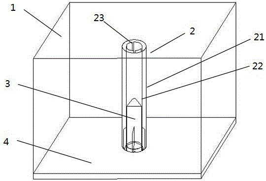
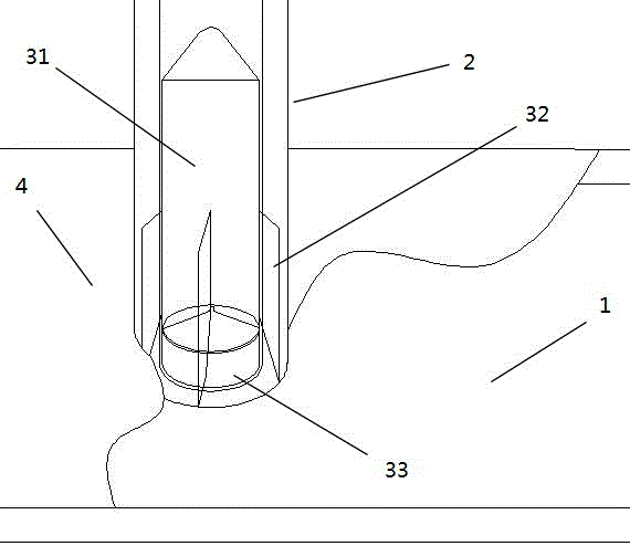
[0053] Embodiment 1: a launch system of a small parachute, characterized in that, the launch system includes a launch tube 2, a casing 1 and a launcher 3; the launch tube 2 is arranged in the casing 1; the launch The launcher 3 is arranged in the launcher 2; the launcher 3 includes a projectile 31 and an igniter 33; the igniter 33 is arranged at the bottom of the launcher 2, and the inner diameter of the launcher 2 is equal to the outer diameter of the igniter 33 The projectile 31 is arranged directly above the igniter 33; the outer diameter of the projectile 31 is equal to the inner diameter of the launch tube 2; the igniter 33 is used to ignite the projectile 31; the projectile 31 After the igniter 33 is ignited, the launch tube 2 can be ejected, and the launch tube 2 is used to pull out the parachute; at least three guide fins 32 are symmetrically arranged on the side wall of the launch body 31; There are empennage slots 23 that are identical in number and matched with the ...

Embodiment 2

[0055] Embodiment 2: a launch system of a small parachute, characterized in that, the launch system includes a launch tube 2, a casing 1 and a launcher 3; the launch tube 2 is arranged in the casing 1; the launch The launcher 3 is arranged in the launcher 2; the launcher 3 includes a projectile 31 and an igniter 33; the igniter 33 is arranged at the bottom of the launcher 2, and the inner diameter of the launcher 2 is equal to the outer diameter of the igniter 33 The projectile 31 is arranged directly above the igniter 33; the outer diameter of the projectile 31 is equal to the inner diameter of the launch tube 2; the igniter 33 is used to ignite the projectile 31; the projectile 31 After the igniter 33 is ignited, the launch tube 2 can be ejected, and the launch tube 2 is used to pull out the parachute; at least three guide fins 32 are symmetrically arranged on the side wall of the launch body 31; There are empennage slots 23 that are identical in number and matched with the ...

Embodiment 3

[0057] Embodiment 3: a launch system of a small parachute, characterized in that, the launch system includes a launch tube 2, a casing 1 and a launcher 3; the launch tube 2 is arranged in the casing 1; the launch The launcher 3 is arranged in the launcher 2; the launcher 3 includes a projectile 31 and an igniter 33; the igniter 33 is arranged at the bottom of the launcher 2, and the inner diameter of the launcher 2 is equal to the outer diameter of the igniter 33 The projectile 31 is arranged directly above the igniter 33; the outer diameter of the projectile 31 is equal to the inner diameter of the launch tube 2; the igniter 33 is used to ignite the projectile 31; the projectile 31 After the igniter 33 is ignited, the launch tube 2 can be ejected, and the launch tube 2 is used to pull out the parachute; at least three guide fins 32 are symmetrically arranged on the side wall of the launch body 31; There are empennage slots 23 that are identical in number and matched with the ...


PUM


Abstract

The invention discloses a launching system of a small parachute, and relates to the field of safety devices, in particular to a small-parachute safe landing device. The launching system comprises a base, an outer cylinder, an inner cylinder and a launcher. The inner cylinder is arranged inside the outer cylinder, and the inner cylinder and the outer cylinder arranged in a concentric circle mode; the inner cylinder and the outer cylinder are both arranged on the base; an igniter is arranged at the portion, located inside the inner cylinder, of the center of the base; the launcher is arranged inside the inner cylinder and located right above the igniter; the igniter is used for igniting the launcher; at least three empennage grooves are formed in the periphery of the inner cylinder; guiding empennages matched with the empennage grooves are arranged on the periphery of the igniter, and the number of the guiding empennages is the same as that of the empennage grooves; the launcher is used for pulling out the parachute. According to the launching system, a launched body is subjected to guiding positioning through the launching cylinders, the parachute in a parachute bin is bulked through an air guide hole, and it is prevented that the parachute is snarled and cannot be normally unfolded.

Description

technical field [0001] The invention relates to the field of safety equipment, in particular to small parachute safety landing equipment. Background technique [0002] The launching system of the small-sized parachute in the prior art generally adopts spring power to start, and the response time of the parachute started by the spring power is long, the response is slow, and the spring is in a compressed state for a long time, and the metal will fatigue and deform, resulting in the reduction of the elastic force of the spring. Spring-powered parachutes are much less safe to use. There will be situations where the parachute responds slowly, the parachute cannot be ejected, etc., and eventually the parachute cannot be opened in time to cause a crash. [0003] The launcher of the launch system of the small-sized parachute in the prior art shoots directly from the inner tube, but the launcher of the prior art is poor in stability, and it is easy to deviate in direction after bei...

Claims


Application Information

Patent Timeline
Patent Type & Authority Applications(China)
IPC IPC(8): B64D17/72
CPCB64D17/725
Inventor 王韶兴钱利强姜文理马瑞印贺云伟李闪
Owner 江苏飞图智能控制技术有限公司
Why Eureka
Try Eureka