
Built-in sewing machine winding mechanism

A winding mechanism and sewing machine technology, applied in the direction of bobbin winding in sewing machines, sewing machine components, sewing equipment, etc., can solve the problems of affecting the working efficiency, stability and reliability of sewing machines, affecting the aesthetics of sewing machines, and low degree of automation. Achieve the effects of superior performance, improved work stability and work efficiency, and a high degree of automation

Active Publication Date: 2017-02-22
中山市金冠电器科技有限公司
View PDF17 Cites 5 Cited by
  • Summary
  • Abstract
  • Description
  • Claims
  • Application Information

AI Technical Summary

Problems solved by technology

[0002] Sewing machines usually use the bobbin thread and upper thread to complete the fabric sewing, and the bobbin thread is provided by the bobbin with the bobbin thread wound in the shuttle. During the specific sewing process, the bobbin will have a temporary lack of thread. Thread operation, if the entire bobbin is replaced, it is too wasteful, but manual winding is too cumbersome, time-consuming and labor-intensive, so it is improved to use the motor transmission mechanism of the sewing machine to complete the automatic winding operation
The winding mechanism of the existing sewing machine has a complex structure, large volume, and unreasonable design. It is placed outside the casing, which not only affects the aesthetics of the sewing machine, but also interferes with the production process, affecting the working efficiency and stability of the sewing machine. , that is, the high failure rate
In addition, the existing sewing machine winding mechanism requires manual observation of the winding situation at any time during the winding process to prevent the winding from being too full, resulting in low automation and low work efficiency

Method used


Image

  • Built-in sewing machine winding mechanism
  • Built-in sewing machine winding mechanism
  • Built-in sewing machine winding mechanism

Examples


Embodiment Construction

[0019] It should be understood that the specific embodiments described here are only used to explain the present invention, not to limit the present invention.

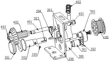
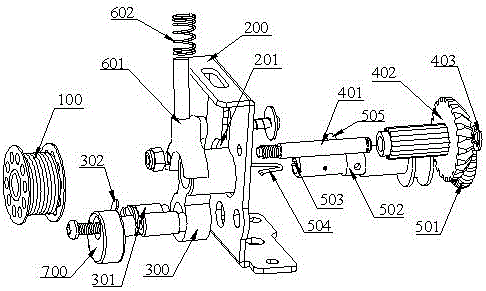
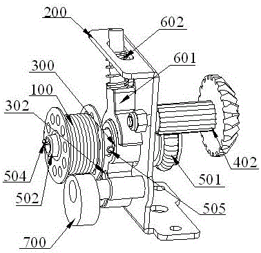
[0020] refer to Figure 1 to Figure 6 , propose an embodiment of a built-in sewing machine winding mechanism of the present invention, the sewing machine includes a casing, a motor transmission mechanism located in the casing, the motor transmission mechanism includes a motor, a main shaft that can rotate with the work of the motor, A driven gear that is set on the main shaft and can rotate with the rotation of the main shaft. The upper end surface of the casing is provided with a storage slot that can accommodate the bobbin 100 at the position corresponding to the position of the driven gear. Simple and practical, reasonable and innovative design.

[0021] The sewing machine winding mechanism of the present invention is built in the casing, the sewing machine winding mechanism can fix the bobbin 100 and can complet...


PUM


Abstract

The invention discloses a built-in sewing machine winding mechanism. A sewing machine comprises a machine shell and a motor transmission mechanism arranged inside the machine shell, the sewing machine winding mechanism is arranged in the machine shell, can fix a shuttle peg and complete automatic winding operation on the shuttle peg, and comprises a support, a swinging connecting rod, a bevel gear mechanism in linkage with the motor transmission mechanism, a winding shaft mechanism capable of rotating along with rotation of the bevel gear mechanism and a poking fork mechanism, the winding shaft mechanism comprises an annular rubber ring which can abut against the bevel gear mechanism and rotate and a winding shaft capable of rotating along with rotation of the annular rubber ring, and the shuttle peg is fixed to the winding shaft and can rotate along with rotation of the annular rubber ring to complete winding. By the utilization of the clutch state between the annular rubber ring and a bevel gear, automatic winding operation on the shuttle peg is completed; the sewing machine winding mechanism is arranged in the machine shell and has the advantages of being reasonable in structural design, high in automation degree, good in working stability and the like.

Description

technical field [0001] The invention relates to the technical field of machinery, in particular to a built-in sewing machine winding mechanism. Background technique [0002] Sewing machines usually use the bobbin thread and upper thread to complete the fabric sewing, and the bobbin thread is provided by the bobbin with the bobbin thread wound in the shuttle. During the specific sewing process, the bobbin will have a temporary lack of thread. Thread operation, if the whole bobbin is replaced, it is too wasteful, but winding by hand is too cumbersome, time-consuming and labor-intensive, so it is improved to complete the automatic winding operation by means of the motor transmission mechanism of the sewing machine. The winding mechanism of the existing sewing machine has a complex structure, large volume, and unreasonable design. It is placed outside the casing, which not only affects the aesthetics of the sewing machine, but also interferes with the production process, affec...

Claims


Application Information

Patent Timeline
Patent Type & Authority Applications(China)
IPC IPC(8): D05B59/00
CPCD05B59/00
Inventor 马冠军张晓胡
Owner 中山市金冠电器科技有限公司
Learn More