
Reagent injection tool for oil field water control and oil stabilizing process measure operation

A chemical and water stabilization technology, applied in wellbore/well components, earthmoving, sealing/packing, etc., can solve problems such as inability to meet the requirements of acidification in the pipe, inability to perform wireline operations, and inability to achieve simultaneous opening and injection of chemical agents.

Pending Publication Date: 2017-02-22
CNOOC ENERGY TECH & SERVICES +1
View PDF6 Cites 3 Cited by
  • Summary
  • Abstract
  • Description
  • Claims
  • Application Information

AI Technical Summary

Problems solved by technology

[0003] Since the AICD controls the flow of fluid from the outside of the pipe to the inside of the pipe, it can only flow in one direction. At present, the sliding sleeve tool is commonly used in the oil field to control the flow between the tubing and the casing, and the steel wire technology is commonly used to control the sliding switch. However, the well deviation of the oil well exceeds 60° When the temperature is high, the steel wire operation cannot be carried out, and the function of the ordinary check valve is simple, and it cannot meet the requirements of acidification and other measures in the pipeline. Water stabilizes oil and satisfies the function of oil well chemical agent injection and other measures
After the AICD water control string is run in, the sand control section of the oilfield needs to use mechanical packers and chemical packers to control water in layers, so downhole tools such as packers need to be set first, and the setting pressure is about 18MPa. Ordinary injection tools do not meet this performance requirement, nor can they realize the functional requirement of synchronously opening the injection agents of each layer

Method used


Image

  • Reagent injection tool for oil field water control and oil stabilizing process measure operation
  • Reagent injection tool for oil field water control and oil stabilizing process measure operation
  • Reagent injection tool for oil field water control and oil stabilizing process measure operation

Examples


Embodiment Construction

[0019] It should be noted that, in the case of no conflict, the embodiments of the present invention and the features in the embodiments can be combined with each other.

[0020] In describing the present invention, it should be understood that the terms "center", "longitudinal", "transverse", "upper", "lower", "front", "rear", "left", "right", " The orientations or positional relationships indicated by "vertical", "horizontal", "top", "bottom", "inner" and "outer" are based on the orientations or positional relationships shown in the drawings, and are only for the convenience of describing the present invention and Simplified descriptions, rather than indicating or implying that the device or element referred to must have a particular orientation, be constructed and operate in a particular orientation, and thus should not be construed as limiting the invention. In addition, the terms "first", "second", etc. are used for descriptive purposes only, and should not be understood ...


PUM


Abstract

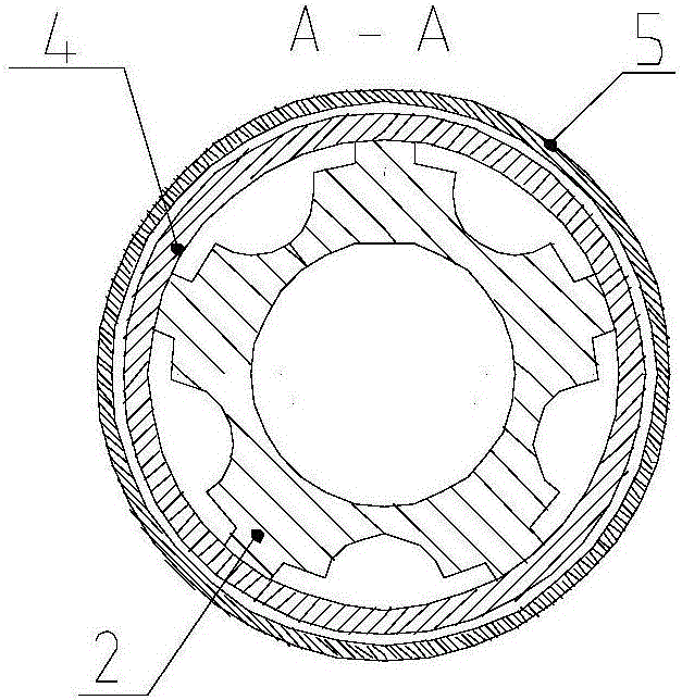
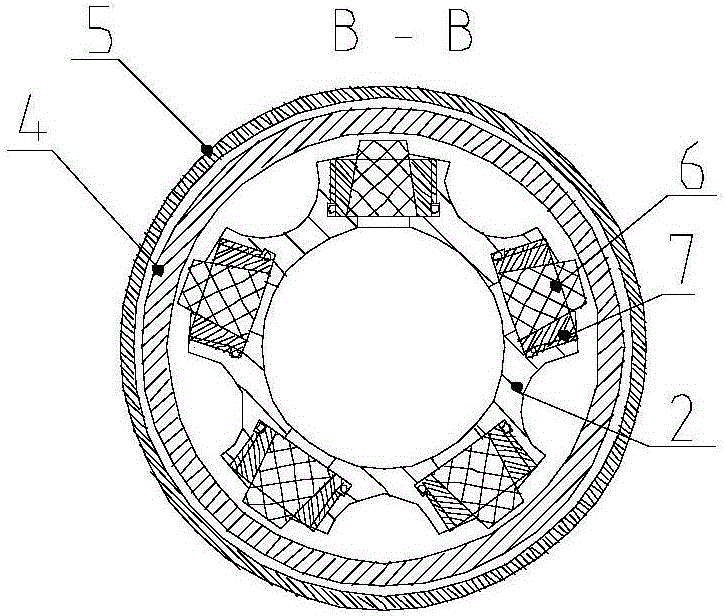
The invention relates to a reagent injection tool for oil field water control and oil stabilizing process measure operation. Two sections of the tool are connected with an oil tubular column and a matched tool respectively, a circular hole is formed in the inner wall of the tool, a soluble part is arranged, the dissolution time of the soluble part is limited within preset time, the inner cavity of the tool is in a sealed state within the preset time, and pressing work can be carried out; after the soluble tool is dissolved, reagent injection work is carried out, a reagent enters the annular cavity of the tool through the circular hole in the inner wall of the tool, the reagent pushes a movable piston to move and presses a spring, a seal cylinder is connected with the movable piston, and the movable piston drives the seal cylinder to switch on a chemical reagent injection valve; after reagent injection ends, the pressure difference of the inside and the outside of the tool is zero, the spring rebounds and pushes the movable piston to return, and the chemical reagent injection valve is switched off. Timed locking, one-way injecting, synchronous switching-on or switching-off and long-term storing of the chemical reagent injection valve can be achieved.

Description

technical field [0001] The invention belongs to the technical field of oil well operation tools, and in particular relates to a chemical injection tool used for an autonomous fluid flow control valve in an oil field. Background technique [0002] With the increase of the production life of the oilfield, the water cut of the oil well gradually increases, and the oil production gradually decreases; the oilfield development has entered the stage of high water cut, and the water cut rises rapidly after the oil well breaks through, which seriously restricts the efficient development of the oilfield; in order to adapt to the stability of the offshore oilfield In order to meet the needs of oil and water control, more and more string technology suitable for intelligent water control in oilfields has been developed, providing new methods to solve the problem of high water cut in field oilfields, so as to realize water control and stable oil in high water cut oil wells and meet the nor...

Claims


Application Information

Patent Timeline
IPC IPC(8): E21B33/138E21B34/06
CPCE21B33/138E21B34/06
Inventor 朱橙解会军李登田发超刘华伟钟宝库李孟超杨德华
Owner CNOOC ENERGY TECH & SERVICES
Learn More