A device that utilizes wave energy to inflate an air floatation platform

An air flotation platform and wave technology, applied in the direction of liquid displacement machinery, variable displacement pump components, piston pumps, etc., can solve the problems of high pressure in the gas storage space, low efficiency of wave energy utilization, and failure of sealing rings, etc., to achieve The effect of improving reliability

Active Publication Date: 2018-04-24
HARBIN ENG UNIV
View PDF8 Cites 0 Cited by
  • Summary
  • Abstract
  • Description
  • Claims
  • Application Information

AI Technical Summary

Problems solved by technology

[0006] 1) The push plate of the device can only receive wave energy in one direction. When the direction of the wave is inconsistent with the direction of travel of the push plate, the utilization efficiency of the wave energy of the device is relatively low;
[0007] 2) The device does not have a mechanism to stop the inflation work. As long as there are waves acting on the push plate, the inflation work will continue, so that the air pressure in the air storage space will continue to rise until the wave cannot push the push plate, which will easily cause gas storage. Risk of excessive pressure in the space;
[0008] 3) The piston rod of the device is directly exposed to seawater, which is easy to corrode or attach pollutants. When it is pulled back and forth, it will rub against the seal ring on the inflator, which will easily cause the seal ring to fail, thus causing the inflator to leak

Method used


Image

  • A device that utilizes wave energy to inflate an air floatation platform
  • A device that utilizes wave energy to inflate an air floatation platform
  • A device that utilizes wave energy to inflate an air floatation platform

Examples


Embodiment Construction

[0023] The present invention will be further described in detail below in conjunction with the accompanying drawings and specific embodiments.

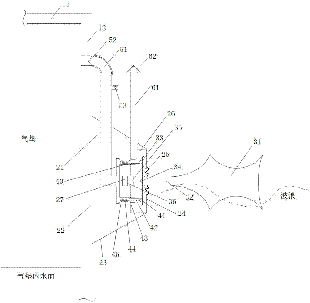
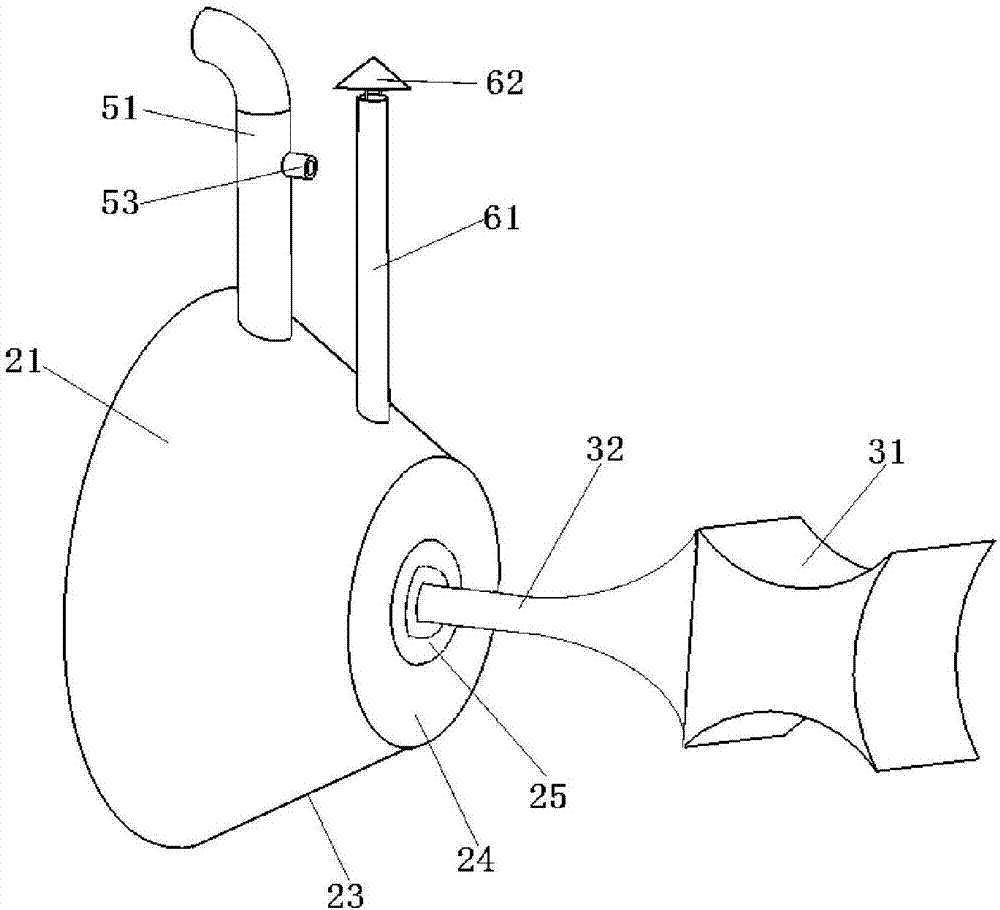
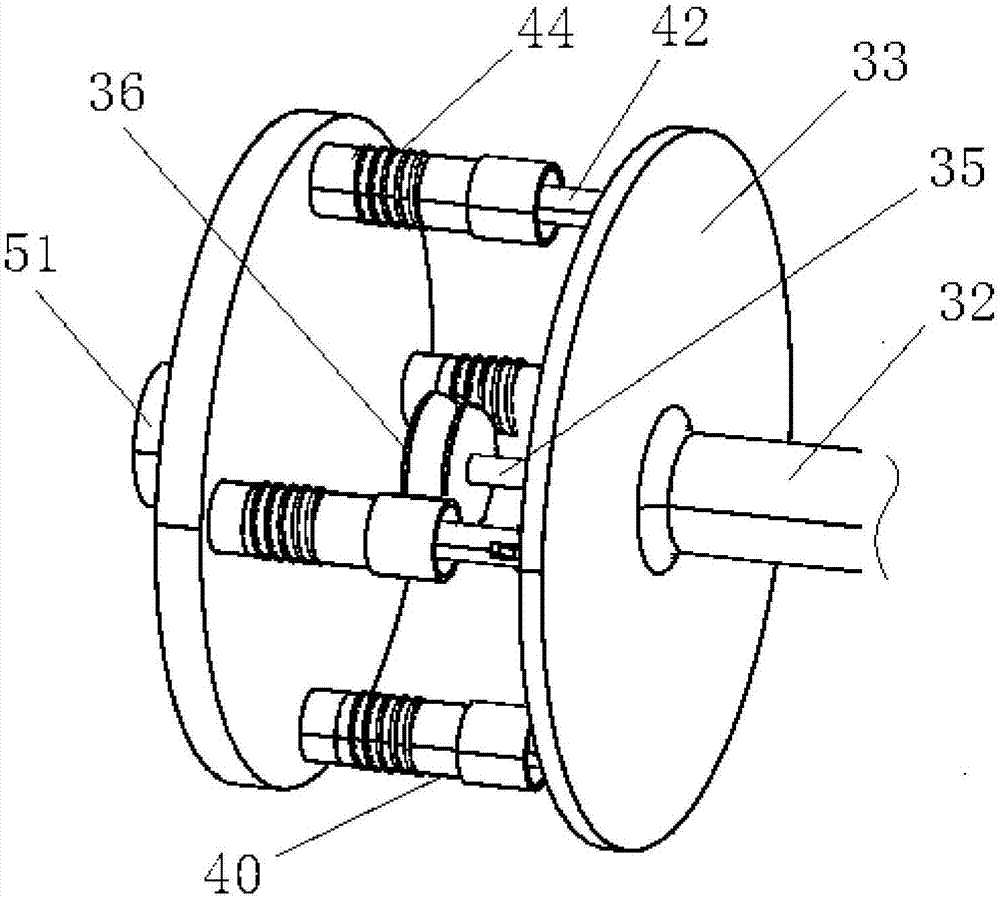
[0024] combine Figure 1 to Figure 5 , the present invention comprises a base 21, a float 31, a pressure plate 33, an air pump 40, an air delivery pipe 51 and an air suction pipe 61, and is characterized in that the base 21 is fixedly connected to the outer wall 12 of the air floating platform, and the float 31 and the pressure plate 33 is fixedly connected, the pump 40 is fixedly connected inside the base 21, one end of the air delivery pipe 51 communicates with the air cushion, the other end communicates with the exhaust port of the pump 40, one end of the suction pipe 61 communicates with the atmosphere, and the other end passes through the air The cavity 26 communicates with the air inlet of the air pump 40 , and the pressing plate 33 can be pushed flat or rotated around the ball hinge 34 to push the piston rod 42 of the air pump ...


PUM


Abstract

The invention provides a device for inflating an air-floating platform by utilizing wave energy. The device comprises a base (21) which is fixed on the outer side wall (12) of the air-floating platform, a floater (31), a pressing plate (33), an inflator (40), an air conveying pipe (51) and an air suction pipe (61); when the pressure of an air cushion is not sufficient, most part of the floater (31) is located below a water surface; under the effect of waves, the floater (31) can drive the pressing plate (33) to upwards and downwards or leftwards and rightwards rotate around a spherical hinge (34) or push and pull the spherical hinge (34) to move back and forth; and the piston rod (42) of the inflator is pushed to inflate the air cushion through the air conveying pipe (51). Under the reciprocating effect of the waves, the air cushion can be inflated continuously until the air pressure of the air cushion is restored to a rated value and the platform floats to normal load draught; and at the time, most part of the floater (31) is exposed out of water, and the device stops working. By adopting the device, the air pressure of the air cushion can be maintained at the rated value so that requirement on the performance of the platform is met.

Description

technical field [0001] The invention relates to an inflating device, in particular to a device for inflating an air floating platform by using wave energy. Background technique [0002] Compared with the conventional barge-type offshore platform, the bending moment and chronic drift force of the air-floating platform in the waves are relatively small, and the heave, pitch, and rolling motion responses are relatively gentle, and the natural cycle of the air-floating platform motion response Longer than barge-type platforms of the same size or displacement, it can effectively avoid the resonance between the platform and the waves. Therefore, air-floating platforms are favored in marine engineering and are used as offshore floating airports, artificial islands, and cargo transportation platforms. [0003] The air floating platform requires a certain pressure of gas to be maintained in the air cushion under the platform. However, the compressed air in the air cushion is likely ...

Claims


Application Information

Patent Timeline
Patent Type & Authority Patents(China)
IPC IPC(8): F04B35/02F04B27/12F04B39/00F04B39/12
CPCF04B27/12F04B35/00F04B39/00F04B39/12
Inventor 郭志群马庆位郝红彬张学栋于一飞陈天文刘树伟刘玉洁刘杰
Owner HARBIN ENG UNIV
Why Eureka
Try Eureka