Self-balancing variable-pitch cone-shaped screw rotor

A conical screw and variable pitch technology, which is applied in the direction of rotary piston pumps, rotary piston machines, and parts of pumping devices for elastic fluids, can solve the problem of increasing the strength of the screw rotor, occupying the suction volume, and gas Interstage leakage and other problems can be achieved to reduce the volume of the working chamber, increase the volume of the working chamber and increase the pumping speed

Inactive Publication Date: 2017-02-22
CHINA UNIV OF PETROLEUM (EAST CHINA)
View PDF10 Cites 9 Cited by
  • Summary
  • Abstract
  • Description
  • Claims
  • Application Information

AI Technical Summary

Problems solved by technology

[0004] In order to solve the eccentric force of the screw rotor in the above literature, the cusp of the section line, the large thickness of the tooth top at the suction end occupies the suction volume, and the small thickness of the tooth top at the exhaust end makes the gas pass through the interstage leakage of the tooth top surface. The larger problem, in order to enrich the types of screw rotors, the present invention proposes a self-balancing variable-pitch conical screw rotor; the screw rotor is conical, from the suction end (I-I) to the exhaust end (VII-VII) ), the lead of the screw rotor (P 1 ,P 2 ,P 3 ) gradually decreases, the thickness of the addendum (S 1 , S 2 , S 3 ) and root thickness (T 1 , T 2 , T 3 ) gradually increases, which can further increase the suction volume of the screw rotor at the suction end (I-I), and effectively prevent the screw rotor from flowing between two adjacent working chamb...

Method used


Image

  • Self-balancing variable-pitch cone-shaped screw rotor
  • Self-balancing variable-pitch cone-shaped screw rotor
  • Self-balancing variable-pitch cone-shaped screw rotor

Examples


Embodiment Construction

[0053] The present invention will be further described below in conjunction with the accompanying drawings and embodiments.

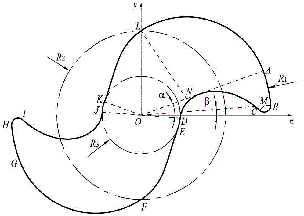
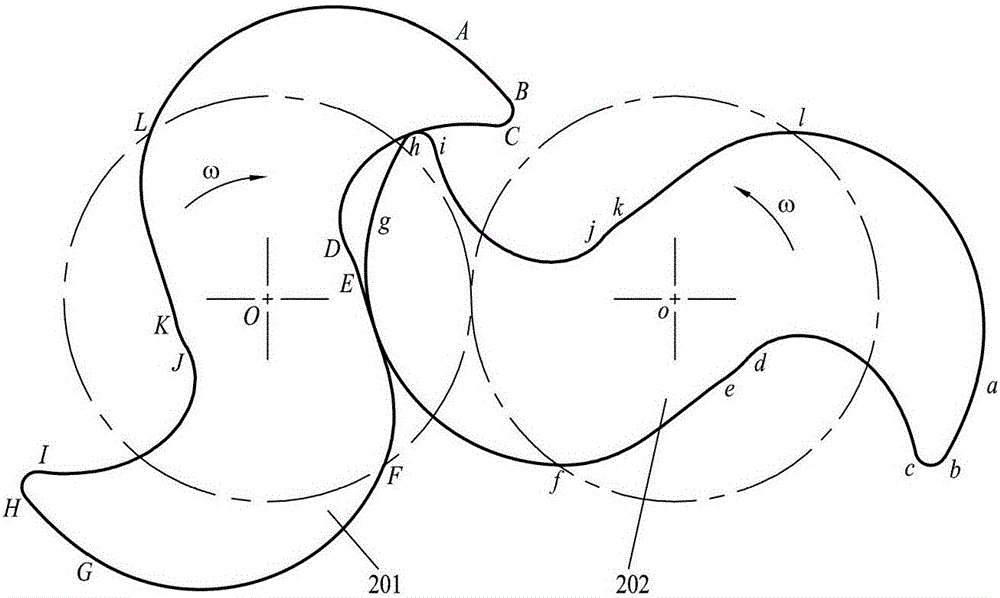
[0054] like figure 1 Shown is the cross-sectional line diagram of the self-balancing variable-pitch conical screw rotor; the cross-sectional line of the screw rotor refers to: use a plane perpendicular to the rotation centerline of the screw rotor to cut off the screw rotor from any axial position, The contour curve obtained at the cross-section; the cross-sectional profile of the screw rotor is surrounded by 12 curves, clockwise as follows: the first addendum arc AB, the first addendum arc BC, and the equidistant curve of the first cycloid CD, the first dedendum arc DE, the envelope EF of the first arc, the first connecting arc FG, the second addendum arc GH, the second tooth tip arc HI, the equidistance of the second cycloid Curve IJ, the second dedendum arc JK, the envelope KL of the second connecting arc, and the second connecting arc LA; the adjac...


PUM


Abstract

The invention discloses a self-balancing variable-pitch cone-shaped screw rotor. The screw rotor is in a cone shape on the whole, tooth crest arc radiuses R1 and leads(P1, P2 and P3) of rotor bodies are gradually reduced from air sucking ends(I-I) to air discharging ends(VII-VII), and tooth root arc radiuses R3, tooth crest thicknesses(S1, S2 and S3) and tooth root thicknesses(T1, T2, T3) are gradually enlarged from the air sucking ends(I-I) to the air discharging ends(VII-VII); a cross section line of any axial position is variable, but all cross section lines are composed of component curves of same type and comprise 12 curves, and every two adjacent curves are completely smoothly connected. According to the self-balancing variable-pitch cone-shaped screw rotor, the sizes of working cavities of the air sucking ends can be efficiently increased, and the sizes of working cavities of the air discharging ends are reduced, so that the rotor bodies each have a large inner-size ratio, and the inter-class sealing performance of the air discharging ends and the strength of the rotor bodies are improved; and the form centers of the cross section lines in any axial position of each rotor body are all located at the rotating center line of the corresponding rotor body, and the dynamic balance performance of the rotor bodies is good.

Description

technical field [0001] The invention relates to a twin-screw vacuum pump, in particular to a self-balancing variable-pitch conical screw rotor suitable for the twin-screw vacuum pump. Background technique [0002] The twin-screw vacuum pump is a positive displacement vacuum pump, which is widely used in petrochemical, food, pharmaceutical, vacuum heat treatment, nano-manufacturing, and national defense technology fields because of its dry and oil-free suction cavity and stable and reliable operation; the core of the twin-screw vacuum pump The components are two screw rotors meshing with each other under synchronous counter-rotating double-rotation motion; the performance of the screw rotor and its cross-sectional profile directly affects the interstage sealing performance, mechanical properties and ultimate vacuum degree of the screw vacuum pump. [0003] The single-head conical screw rotor disclosed in patent CN101351646 has a large outer diameter at the suction end and a s...

Claims


Application Information

Patent Timeline
IPC IPC(8): F04C29/00F04C18/16F04C25/02
CPCF04C18/084F04C18/16F04C25/02F04C2240/20F04C2250/201
Inventor 王君崔锋张凌宏刘强魏蜀红
Owner CHINA UNIV OF PETROLEUM (EAST CHINA)
Why Eureka
Try Eureka