Conical screw rotors of twin-screw vacuum pump

A conical screw and vacuum pump technology, which is applied to the components, pumps, and pump elements of the pumping device for elastic fluids, can solve the problems of limited enlargement effect, limited performance improvement effect, incomplete meshing, etc. The effect of reducing the volume of the working chamber, increasing the content ratio, and improving the ultimate vacuum degree

Pending Publication Date: 2020-02-21
CHINA UNIV OF PETROLEUM (EAST CHINA)
View PDF3 Cites 5 Cited by
  • Summary
  • Abstract
  • Description
  • Claims
  • Application Information

AI Technical Summary

Problems solved by technology

Chinese patent (publication number CN105422448A) discloses a screw rotor with variable tooth width and variable pitch. The screw rotor has a large suction volume and internal volume ratio, but the parallel shaft structure has limited effect on increasing the internal volume ratio.
Chinese patent (authorized notification number CN205805908U) discloses a conical screw rotor and its twin-screw vacuum pump, using a three-stage conical twin-screw structure, which increases the suction volume and internal volume ratio, but has limited performance improvement , and it is not easy to ensure the sealing effect between the twin-screw rotor and the pump chamber
Chinese patent (patent No. CN 104141606A) proposes a conical twin-screw compression pump, which uses a 5:3 transmission of female and male conical screws, which has a high compression coefficient in theory, but the cross-axis engagement of the two plane sections There can only be one straight line in the lower contact line, and the multi-head planar line will be incompletely meshed or not meshed in the case of cross-axis meshing, and the sealing performance between the two screws cannot be guaranteed.

Method used


Image

  • Conical screw rotors of twin-screw vacuum pump
  • Conical screw rotors of twin-screw vacuum pump
  • Conical screw rotors of twin-screw vacuum pump

Examples


Embodiment Construction

[0056] The present invention will be further described below in conjunction with the accompanying drawings and embodiments.

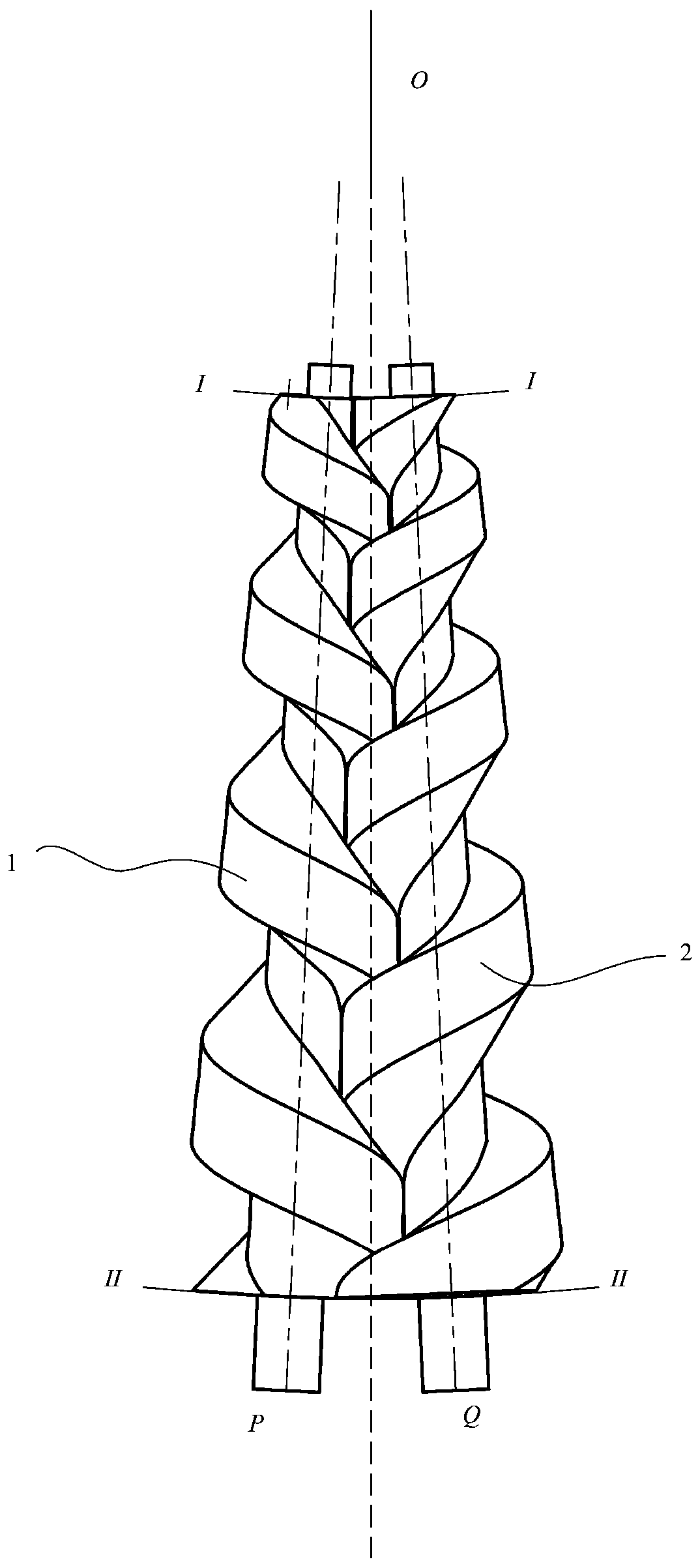
[0057] Such as figure 1 As shown, it is the meshing diagram of two screw rotors, including: left conical screw rotor 1, right conical screw rotor 2, left conical screw rotor 1 and right conical screw rotor 2 are connected from low pressure end II-II to high pressure end Ⅰ-Ⅰ is a linear conical shape, that is, the pitch circle radius, tooth top radius and tooth bottom radius of the left conical screw rotor 1 and the right conical screw rotor 2 are linearly reduced;

[0058] In the working engagement state, the rotation axis OP of the left conical screw rotor 1 and the rotation axis OQ of the right conical screw rotor 2 intersect at one point, the intersection point is O, and the angle between the two rotation axes is ∠POQ=θ, which is taken as The value range is 0°<θ<90°;

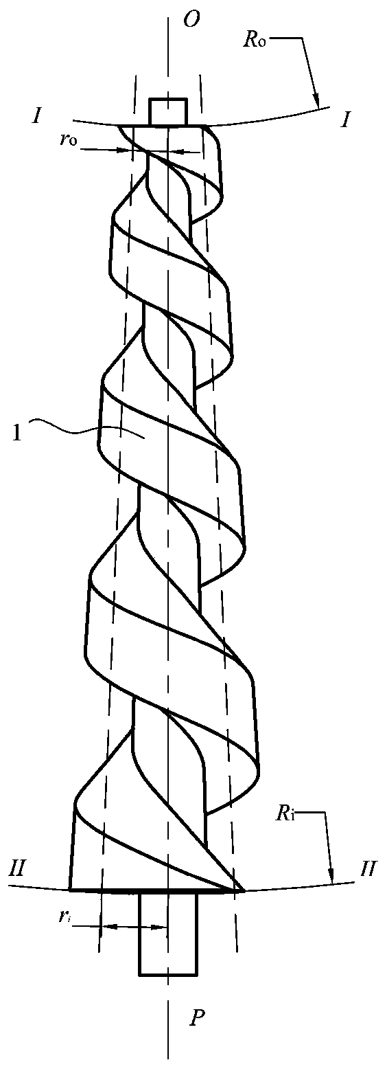
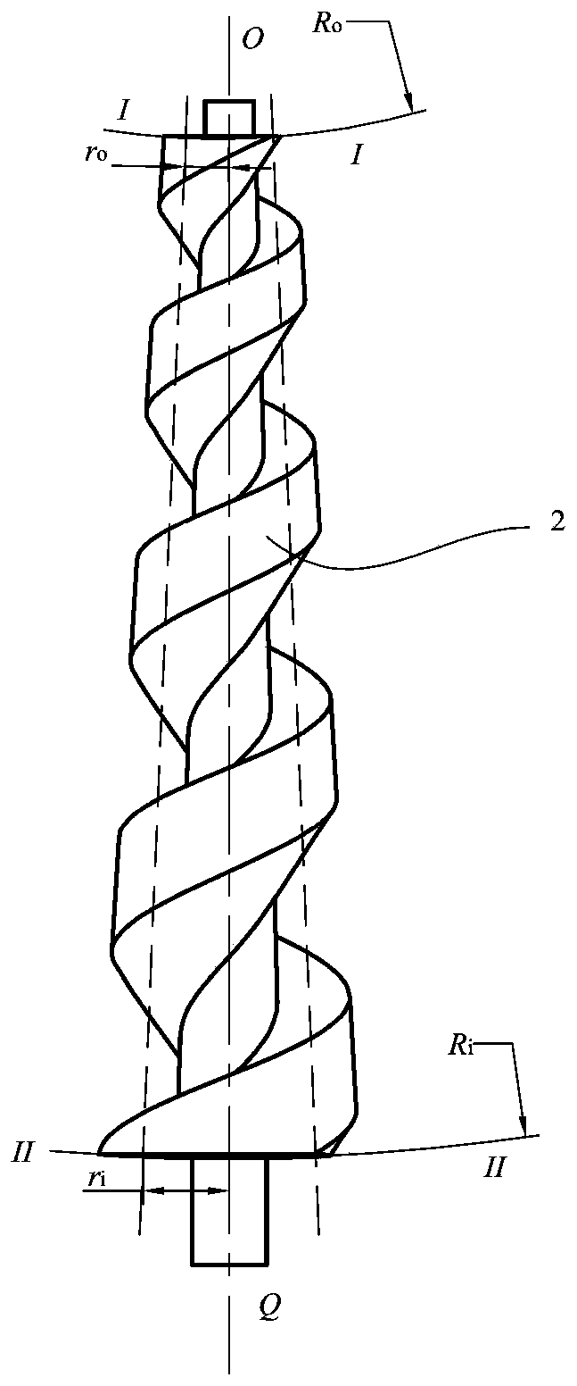
[0059] Such as figure 2 As shown, it is a three-dimensional diagram of the lef...


PUM


Abstract

The invention discloses conical screw rotors of a twin-screw vacuum pump. The left conical screw rotor (1) comprises a high-pressure end concave spherical face, a low-pressure end convex spherical face and four tooth faces, and the four tooth faces are a left conical tooth top face (11), a left conical oblique tooth face (12), a left conical tooth root face (13) and a left conical concave tooth face (14). The right conical screw rotor (2) comprises a high-pressure end concave spherical face, a low-pressure end convex spherical face and four tooth faces, and the four tooth faces are a right conical tooth top face (21), a right conical oblique tooth face (22), a right conical tooth root face (23) and a right conical concave tooth face (24). The left conical screw rotor (1) and the right conical screw rotor (2) can achieve cross axial meshing with the transmission ratio of 1:1. a larger air suction volume is achieved under the same structure parameters, a large effective volumetric rate is achieved, the pumping speed of the twin-screw vacuum pump is increased, the volume of a work cavity of the exhaust end is reduced, large content ratio and compression ratio are achieved, and the limit vacuum degree of the vacuum pump can be increased.

Description

technical field [0001] The invention relates to a twin-screw vacuum pump, in particular to a conical screw rotor suitable for a twin-screw vacuum pump. Background technique [0002] The twin-screw vacuum pump is a rotary positive displacement vacuum pump. A pair of intermeshing screw rotors perform synchronous and opposite double-rotation movements in the pump chamber to realize the periodic change of the volume of the working chamber and complete the process of gas suction, compression and discharge. Vacuum is formed at the inlet of the pump; the twin-screw vacuum pump has the advantages of dry oil-free, stable operation, less wearing parts, low vibration and noise, and is widely used in the fields of aviation, electronics, petrochemical and nuclear industries. [0003] The vacuum pump produces a large compression ratio during the working process, and the two screw rotors that need to mesh with each other have a large internal volume ratio. The internal volume ratio is the ...

Claims


Application Information

Patent Timeline
Patent Type & Authority Applications(China)
IPC IPC(8): F04C25/02F04C18/16F04C18/56F04C29/00
CPCF04C18/16F04C18/565F04C25/02F04C29/00F04C2240/20
Inventor 王君武萌谈庆鹏赵胜李祥艳奚周瑾
Owner CHINA UNIV OF PETROLEUM (EAST CHINA)
Why Eureka
Try Eureka