Straight pipe structure for underwater anti-clogging and drag reduction

A straight pipe and anti-blocking technology, which is applied to pipe components, pipes/pipe joints/fittings, mechanical equipment, etc., can solve problems such as pipe blockage, inner wall wear of pipe fittings, and large water flow resistance of ordinary pipe fittings, so as to reduce resistance and avoid The effect of hydraulic loss

Active Publication Date: 2020-06-05
泰州学院
View PDF7 Cites 0 Cited by
  • Summary
  • Abstract
  • Description
  • Claims
  • Application Information

AI Technical Summary

Problems solved by technology

It is well known that petroleum, hydrate, ore and other resources contain particulate matter. During the flow process, the particles will settle due to the influence of the gravity of the particles. Common pipe fittings have the following disadvantages when transporting such media: After the fluid containing particulate matter enters the ordinary pipe fittings, due to the gravity Influenced by the influence of high-density particles, the velocity decreases and settles, the fluid moves in the center of the pipe fittings, and the particles move at the bottom of the pipe fittings. As the particle velocity continues to decrease, the particles at the bottom of the pipe fittings accumulate, which not only leads to blockage of the pipe fittings but also causes pipe fittings Premature wear of the inner wall; the pipe fittings are used underwater, especially in the marine environment. Due to the viscosity of the water flow, a boundary layer is formed when the water flows through the outer surface of the pipe fitting. The greater the water velocity, the thicker the boundary layer, and the thickness of the boundary layer reaches a certain level The surface of the pipe is separated from the surface of the pipe, forming a boundary layer separation, resulting in the formation of a symmetrical vortex behind the pipe. The larger the vortex area, the smaller the pressure, and the pressure of the water flow in front of the pipe is high, so the pressure difference between the front and back of the pipe is formed, resulting in resistance; ordinary pipes are smooth On the surface, this kind of boundary layer separates early, the vortex area formed behind the pipe fitting is small, and the pressure difference between the front and back of the pipe fitting is large, resulting in large water flow resistance of ordinary pipe fittings underwater

Method used


Image

  • Straight pipe structure for underwater anti-clogging and drag reduction
  • Straight pipe structure for underwater anti-clogging and drag reduction
  • Straight pipe structure for underwater anti-clogging and drag reduction

Examples


Embodiment Construction

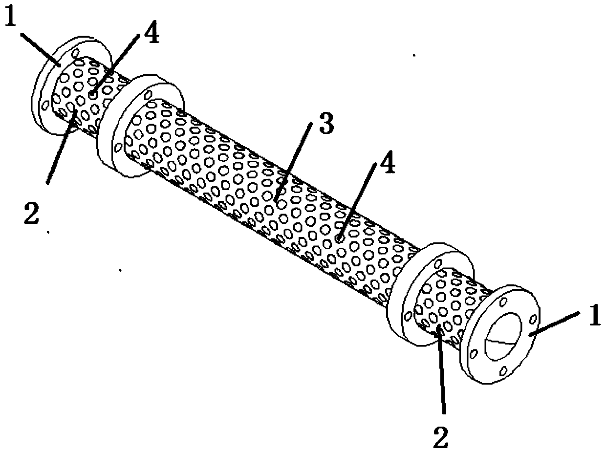
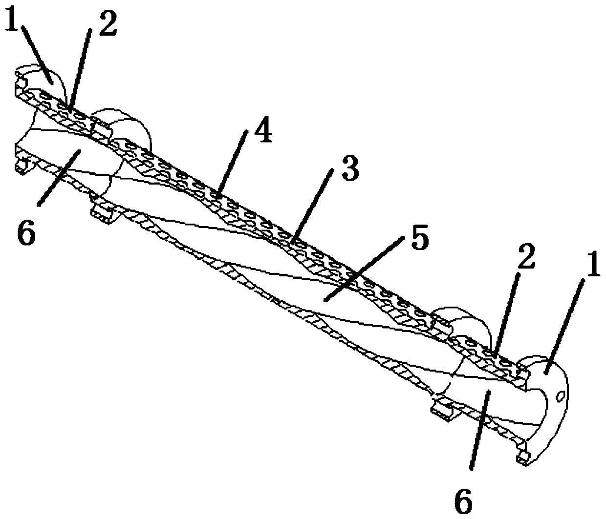
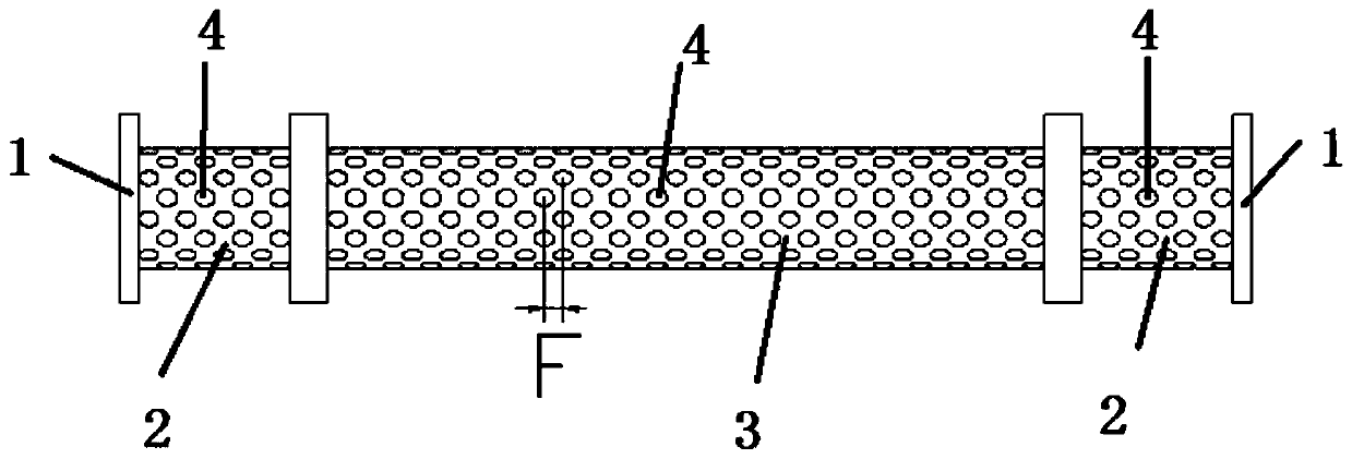
[0023] As shown in the accompanying drawings, a straight pipe structure for underwater anti-blocking and drag reduction includes a main pipe section 3 with a plurality of main spiral grooves 5 inside the flow channel, and two rotary pipes respectively arranged at both ends of the main pipe section 3. The connecting section 2 , the main pipe section 3 and the connecting section 2 are respectively provided with a plurality of pits 4 on their outer surfaces. A plurality of dimples 4 are alternately and evenly distributed on the outer surfaces of the main pipe section 3 and the transition section 2 . The hydraulic diameter of the transition section 2 is equal to the hydraulic diameter D of the main pipe section 3 , and correspondingly, the outer diameter of the transition section 2 is also equal to the outer diameter E of the main pipe section 3 .

[0024] The transition section 2 has a gradual spiral groove 6 connected to the main spiral groove 5, and the gradual spiral groove 6 ...


PUM


Abstract

An underwater blockage preventing and resistance reducing straight pipe structure comprises a main pipe section and a switching section which is arranged on at least one of the two end portions of the main pipe section, wherein a runner of the man pipe section is internally provided with a plurality of main spiral grooves. The switching sections are internally provided with gradual change spiral grooves connected with the main spiral grooves. The gradual change spiral grooves extend outwards from the positions, connected with the main pipe section, of the switching sections, and the groove depth is gradually changed and becomes shallow. A plurality of pits are distributed in the outer surfaces of the main pipe section and the switching sections in a staggered manner. The circular sections of the switching sections are gradually developed into the multiple spiral sections in a transition manner, additional hydraulic power losses caused by sudden changing of the runner section area are avoided, fluid is gradually transferred to be in the rotational flow state, the fluid containing particles rotationally flows in the runner of the main pipe section, the particles are subjected to the rotational flow acting force, leave the bottom of the runner through the rotational flow acting force and are in a suspension state in the runner, and therefore the problem that the particles are settled in a bend, and the runner is blocked is solved. Meanwhile, the pits are formed in the outer surface of the runner, and resistance generated by water flow boundary layer separation is reduced.

Description

technical field [0001] The invention relates to an underwater straight pipe structure for preventing blocking and reducing drag. Background technique [0002] The rapid development of the global economy and the shortage of land resources have promoted the development process of marine mineral resources. At present, the well-known marine mineral resources include oil, placer, combustible ice, manganese metal nodules, etc. For the development of such resources, its important The step is the delivery process of the pipe fittings. It is well known that petroleum, hydrate, ore and other resources contain particulate matter. During the flow process, the particles will settle due to the influence of the gravity of the particles. Common pipe fittings have the following disadvantages when transporting such media: After the fluid containing particulate matter enters the ordinary pipe fittings, due to the gravity Influenced by the influence of high-density particles, the velocity decr...

Claims


Application Information

Patent Timeline
Patent Type & Authority Patents(China)
IPC IPC(8): F16L55/045
CPCF16L55/045
Inventor 王健丁剑刘厚林赵振江宋向前王临茹郭沁涵
Owner 泰州学院
Why Eureka
Try Eureka