Hydraulic gravity type clocked flip-flop

A gravitational, trigger technology, applied in instruments, devices for measuring time intervals, time interval measurement with drive mechanisms, etc., can solve problems such as effects affecting timing

Active Publication Date: 2017-02-22
GAOYOU GAONONG MACHINERY FITTINGS
View PDF5 Cites 1 Cited by
  • Summary
  • Abstract
  • Description
  • Claims
  • Application Information

AI Technical Summary

Problems solved by technology

For the two timing technologies mentioned above, the spring timing has a service life because of the deformation of the spring, so the spring timing technology has a certain service life; as for th

Method used


Image

  • Hydraulic gravity type clocked flip-flop
  • Hydraulic gravity type clocked flip-flop
  • Hydraulic gravity type clocked flip-flop

Examples


Embodiment Construction

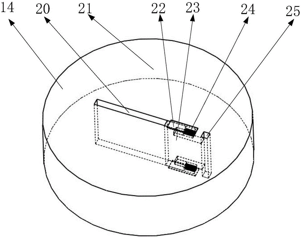
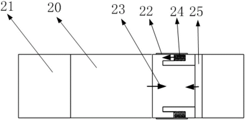
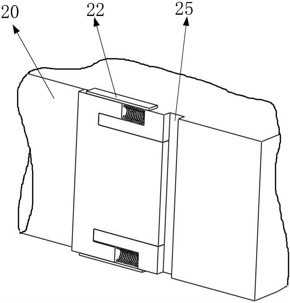
[0028] Such as Figure 6 , 7 As shown, it includes a support cover, a vibration spring, a magnetic snap ring, a vibration ring, a first magnetic ring, a housing, a support ring, a trigger spring, a trigger ring, a magnetic ring, a pillar, a top cover, a gravity plug, a bottom plate, and an impact ring , cardboard, such as Figure 8 As shown, the top cover is installed on the upper end of the housing, the support cover is installed on the top cover through the pillars, and the circular clip is installed on the upper end of the housing; the magnetic snap ring is a permanent magnet, and is nested on the outer edge of the housing and the top cover On the surface, the magnetic snap ring is located on the upper side of the card plate; the vibration ring is made of magnetically conductive material, and is nested on the outer edge surface of the upper side of the housing. One end of the vibration spring is installed on the lower side of the support cover, and the other end is install...


PUM


Abstract

The invention belongs to the technical field of mechanical timing, and particularly relates to a hydraulic gravity type clocked flip-flop which comprises a magnetic clamp ring, a vibrating ring, a casing, a trigger spring, a trigger ring, a magnetic conductive ring, a gravity plug and an impact ring, wherein a liquid medium is in the casing; and the gravity plug moves from the upper end of the casing to the lower end. After a timer is subjected to vibration, during movement, magnetic force of the vibrating ring and a first magnetic ring is reduced, the vibrating ring collides with the lower side of the magnetic clamp ring through the impact ring, magnetic force which the gravity plug is subjected to is reduced, the gravity plug begins to move downwards, and timing starts. When the gravity plug moves to be near a base plate, the gravity plug drives the trigger ring to move, the trigger ring collides with the magnetic conductive ring, and the impact force can trigger an external device. The gravity plug is subjected to lubricating and air insulating effects of hydraulic oil, the contact wall between the gravity plug and the casing is not oxidized, so that the timer has the advantages of being long in service life; due to no participation of electric power, the use range is very wide; and the hydraulic gravity type clocked flip-flop has a good use effect.

Description

[0001] Technical field [0002] The invention belongs to the technical field of mechanical timing, in particular to a hydraulic gravity timing trigger. Background technique [0003] Timing technology From the traditional mechanical spring timing to the most widely used electronic timing technology, timing technology can be described as a wide variety. For the two timing technologies mentioned above, the spring timing has a service life because of the deformation of the spring, so the spring timing technology has a certain service life; as for the electronic timing technology, it is limited by power. In some special occasions, if there is no The location of electricity, or the situation of unstable electricity will affect the timing effect. Therefore, designing a timer that does not use electricity and has a long service life will have certain application prospects. [0004] The present invention designs a hydraulic gravity timing trigger to solve the above problems. Conten...

Claims


Application Information

Patent Timeline
IPC IPC(8): G04F3/00
CPCG04F3/00
Inventor 冯林
Owner GAOYOU GAONONG MACHINERY FITTINGS
Why Eureka
Try Eureka