A hydraulic gravity timing trigger
A gravity and trigger technology, which is applied to instruments, devices for measuring time intervals, and time interval measurement with driving mechanisms, etc., can solve problems affecting timing effects and other issues
- Summary
- Abstract
- Description
- Claims
- Application Information
AI Technical Summary
Problems solved by technology
Method used
Image
Examples
Embodiment Construction
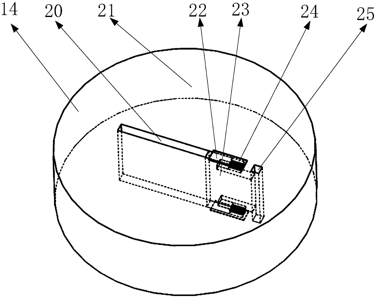
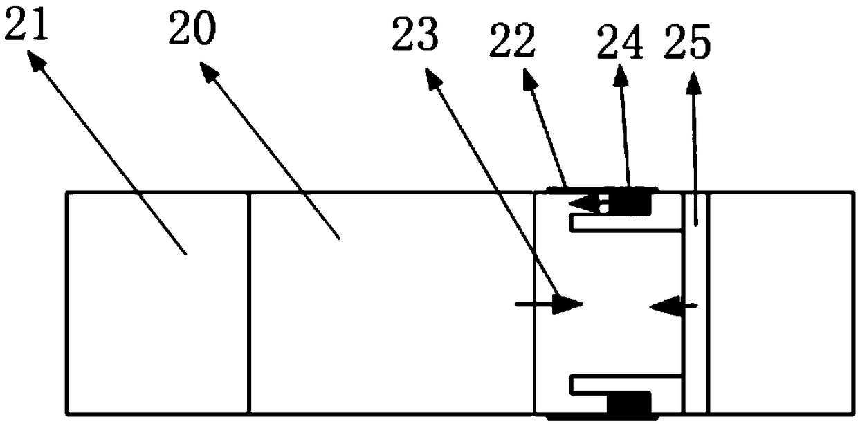
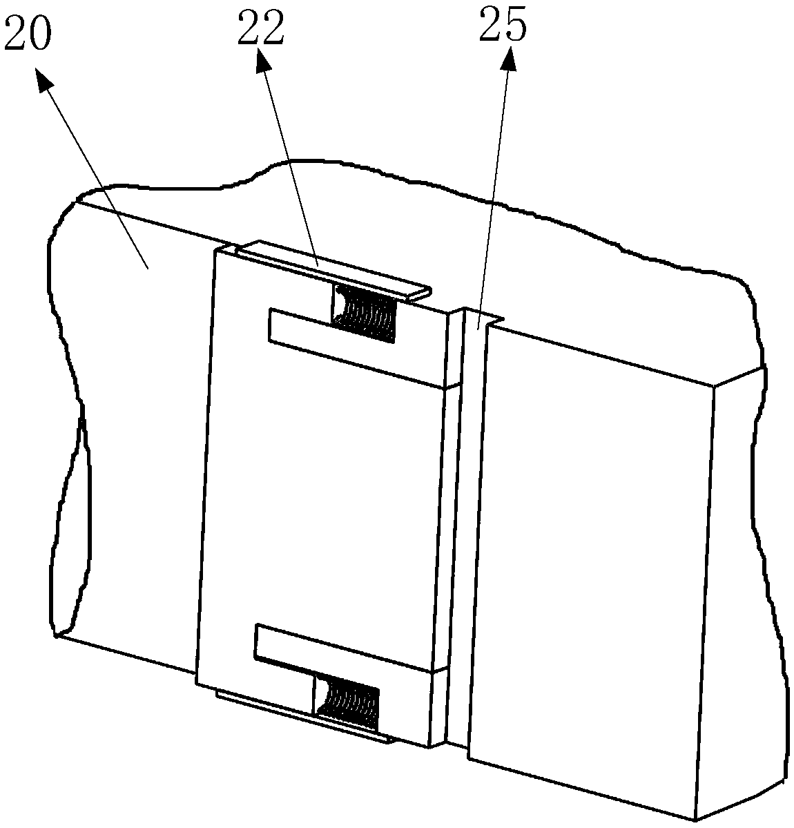
[0027] like Image 6 , 7 As shown, it includes a support cover, a vibration spring, a magnetic snap ring, a vibration ring, a first magnetic ring, a housing, a support ring, a trigger spring, a trigger ring, a magnetic ring, a pillar, a top cover, a gravity plug, a bottom plate, and an impact ring , cardboard, such as Figure 8 As shown, the top cover is installed on the upper end of the housing, the support cover is installed on the top cover through the pillars, and the circular clip is installed on the upper end of the housing; the magnetic snap ring is a permanent magnet, and is nested on the outer edge of the housing and the top cover On the surface, the magnetic snap ring is located on the upper side of the card plate; the vibration ring is made of magnetically conductive material, and is nested on the outer edge surface of the upper side of the housing. One end of the vibration spring is installed on the lower side of the support cover, and the other end is installed o...
PUM
 Abstract
Description
Claims
Application Information
 - R&D
- Intellectual Property
- Life Sciences
- Materials
- Tech Scout
- Unparalleled Data Quality
- Higher Quality Content
- 60% Fewer Hallucinations
Browse by: Latest US Patents, China's latest patents, Technical Efficacy Thesaurus, Application Domain, Technology Topic, Popular Technical Reports.
© 2025 PatSnap. All rights reserved.Legal|Privacy policy|Modern Slavery Act Transparency Statement|Sitemap|About US| Contact US: help@patsnap.com


