Anti-interference method for automatic positioning of optical touch screen

An optical touch screen and automatic positioning technology, applied in the input/output process of data processing, instruments, electrical digital data processing, etc., can solve problems such as difficult to accurately calculate vertices, complex light source, brightness interference, etc., and achieve optical touch screen Automatic positioning for accurate results

Active Publication Date: 2017-02-22
南京仁光电子科技有限公司
View PDF4 Cites 2 Cited by
  • Summary
  • Abstract
  • Description
  • Claims
  • Application Information

AI Technical Summary

Problems solved by technology

However, in actual use, the various light sources in the original pictures taken by the camera are more complicated, such as figure 1 As shown, if the original calibration image (101) is used to directly calculate the calibration point, the area indicated by (103) in the figure has a large interference with the brightness of the block (102) in the overall image, so that it is difficult to accurately calculate the vertices of each square

Method used


Image

  • Anti-interference method for automatic positioning of optical touch screen
  • Anti-interference method for automatic positioning of optical touch screen
  • Anti-interference method for automatic positioning of optical touch screen

Examples


Embodiment Construction

[0033] In order to make the object, technical solution and advantages of the present invention more clearly, the present invention will be further described in detail below in conjunction with the accompanying drawings and specific embodiments.

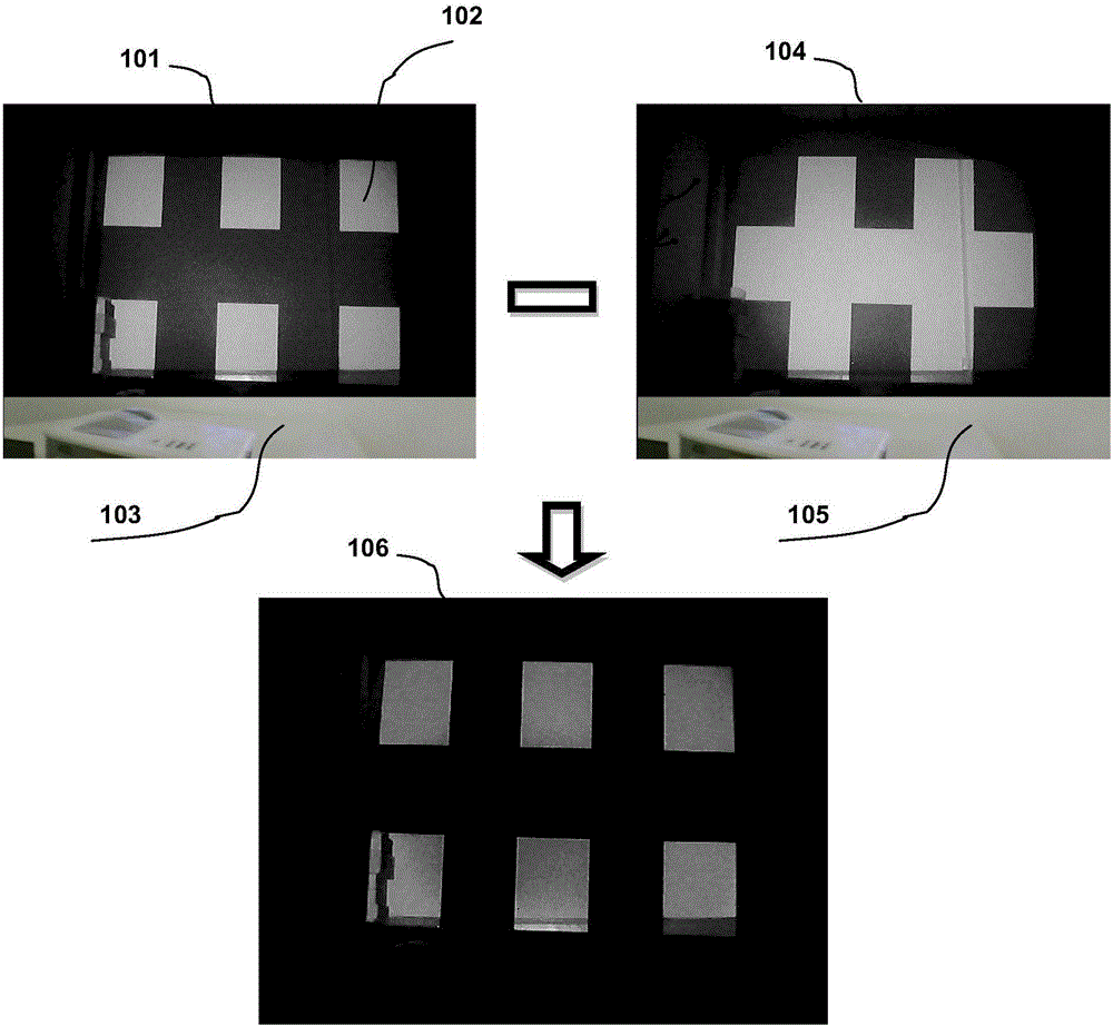
[0034] An embodiment of the present invention provides an anti-interference method in automatic positioning of an optical touch screen, such as figure 1 As shown, (101) is a calibration original image captured by the camera, and the vertices of the six squares referred to in the figure (102) are the calibration points. The purpose of automatic calibration is to accurately extract these The position coordinates of the vertex.

[0035] In use, since the ambient light is constantly changing, especially when the surrounding ambient light is relatively bright, the discrimination between the positioning blocks and the environmental image is not very obvious. Simply relying on the graph (101) to calculate the vertices of the blocks needed f...


PUM


Abstract

The invention discloses an anti-interference method for the automatic positioning of an optical touch screen. The method comprises a method for enhancing a contrast ratio of an image near a calibration point to a surrounding environment image. The method also comprises the following steps of: 1) enhancing a luminance difference between the image near the calibration point and the surrounding environment image, and 2) enhancing the smooth degree of the edge of the image near the calibration point. By use of the anti-interference method, the anti-ambient light interference ability of the automatic positioning of the optical touch screen is improved.

Description

technical field [0001] The invention relates to the technical field of optical touch screens, in particular to an anti-interference method in automatic positioning of optical touch screens. Background technique [0002] An automatic positioning method for an optical touch screen is disclosed in the patent described in the application number 2010201357371. In this patent, an automatic positioning method is adopted in device initialization in order to realize the position coincidence of the control light spot and the cursor on the display screen. The method is to use a quadrilateral to approximate the display area in the captured image: first identify the four vertices of the rectangle where the entire display area is located, and then use the relative position of the control light point relative to the four vertices, and use the geometric relationship to determine the relative position of the control light point. position on the display screen. Using this method to do camer...

Claims


Application Information

Patent Timeline
Patent Type & Authority Applications(China)
IPC IPC(8): G06F3/041G06F3/042
CPCG06F3/0418G06F3/0425
Inventor 谭登峰
Owner 南京仁光电子科技有限公司
Why Eureka
Try Eureka