Rotor production equipment for air suspension centrifugal compressor

A centrifugal compressor and air suspension technology, applied in the field of compressors, can solve the problem of inaccurate installation position of fan blades, achieve the effect of high degree of automation, improve accuracy and reduce production cost

Active Publication Date: 2020-03-24
HUZHOU TEACHERS COLLEGE
View PDF8 Cites 1 Cited by
  • Summary
  • Abstract
  • Description
  • Claims
  • Application Information

AI Technical Summary

Problems solved by technology

[0005] The purpose of the present invention is to address the deficiencies of the prior art, by setting a precise positioning mechanism to cooperate with the disk transmission mechanism, the disk is precisely positioned at a fixed position, and then several groups of blades

Method used


Image

  • Rotor production equipment for air suspension centrifugal compressor
  • Rotor production equipment for air suspension centrifugal compressor
  • Rotor production equipment for air suspension centrifugal compressor

Examples


Embodiment 1

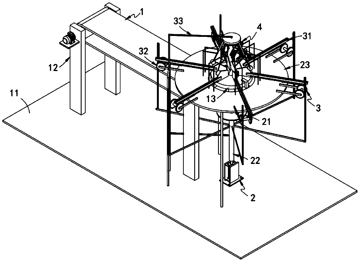
[0070] Such as figure 1 As shown, a rotor production equipment for air suspension centrifugal compressors, including:

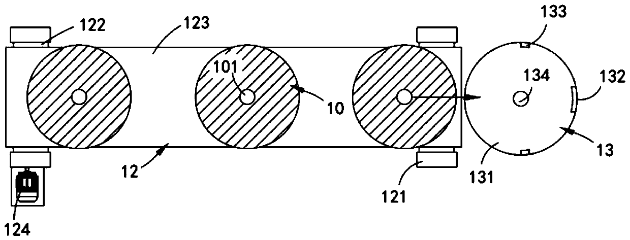
[0071] A disc transport mechanism 1, the disc transport mechanism 1 comprising a base 11, a first conveying assembly 12 disposed on the base 11, and a carrying assembly 13 disposed at the output end of the first conveying assembly 12;

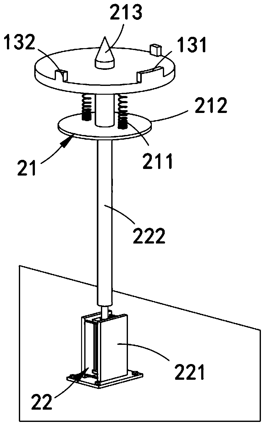
[0072] The precise positioning mechanism 2, the precise positioning mechanism 2 includes a deflection correction component 21 elastically connected to the bearing component 13 and arranged coaxially with it, fixedly connected with the deflection correction component 21 and driving the deflection correction component 21 along the vertical direction The drive assembly 22 moving up and down and the limit assembly 23 located above the bearing assembly 13 and installed on the base 11;

[0073] The blade transmission mechanism 3, the blade transmission mechanism 3 includes a plurality of second transmission components 31 arranged o...

Embodiment 2

[0111] Such as Figure 7 , Figure 13 and Figure 14 As shown, the components that are the same as or corresponding to those in the first embodiment are marked with the corresponding reference numerals in the first embodiment. For the sake of simplicity, only the differences from the first embodiment will be described below. The difference between this embodiment two and embodiment one is:

[0112] further, such as Figure 7 , Figure 13 and Figure 14 As shown, the tightening assembly 33 includes:

[0113] Lifting member 331, said lifting member 331 includes a pulling plate 3311 located at the upper end of the disc 10 and coaxially arranged with the disc 10 and an intermittent unit 3312 controlling the movement of the pulling plate 3311 up and down; and

[0114] A swing member 332, the swing member 332 includes a mounting frame a3321 installed on the frame b231, a rotating shaft b3322 fixedly arranged on the mounting frame a3321, a transmission rod a3323 rotatingly arrang...


PUM


Abstract

The invention relates to rotor production equipment for an air suspension centrifugal compressor. The rotor production equipment comprises a disc conveying mechanism, a precise positioning mechanism,a blade conveying mechanism and a welding robot; the disc conveying mechanism comprises a machine seat, a first conveying assembly and a bearing assembly; the precise positioning mechanism comprises adeviation rectifying assembly, a driving assembly fixedly connected with the deviation rectifying assembly and driving the deviation rectifying assembly to move up and down in the vertical directionand a limiting assembly positioned above the bearing assembly and mounted on the machine seat; the blade conveying mechanism comprises a plurality of groups of second conveying assemblies arranged onthe limiting assembly and arrayed in the circumferential direction of a disc, pushing assemblies in one-to-one correspondence with the input ends of the second conveying assemblies and working synchronously with the driving assembly as well as hooping assemblies arranged above the second conveying assemblies and in synchronous action with the driving assembly; and the welding robot is used for carrying out one-by-one welding and assembling of a plurality of groups of blades accurately positioned on the disc. According to the rotor production equipment for the air suspension centrifugal compressor, the technical problem of inaccurate precision in the installation position during assembling of the blades of a fan can be solved.

Description

technical field [0001] The invention relates to the technical field of compressors, in particular to a rotor production equipment for air suspension centrifugal compressors. Background technique [0002] As a common equipment including fire protection products, fans include hybrid fans, axial flow fans and centrifugal fans. The assembly of fan blades refers to the circumferential arrangement of multiple fan blades of the fan on the fan hub by welding. The outer surface of the fan has been formed into a fan product. The assembly of the blades of the traditional axial flow fan is manual, which is labor-intensive and time-consuming. There are many errors in the manual production, and the product defective rate is very high. [0003] The patent document with the patent number CN201710695581 discloses a fan blade assembly machine and a fan blade assembly method. Fan blade assembly machine, which includes a frame, a hub fixing device, a blade fixing device, and an index limiting ...

Claims


Application Information

Patent Timeline
IPC IPC(8): B23K31/02B23K37/00B23K37/04
CPCB23K31/02B23K37/00B23K37/0435
Inventor 张长森曹枫
Owner HUZHOU TEACHERS COLLEGE
Why Eureka
Try Eureka