High current anti-swing spring terminal

An anti-swing, high-current technology, applied in circuits, electrical components, parts of connecting devices, etc., can solve the problem of electrical wiring that cannot flow current, the contact area between male inserts and insert springs is small, and it is not suitable for higher power electrical wiring. requirements and other issues to achieve the effect of avoiding potential safety hazards, good electrical conductivity, safe and stable operation

Active Publication Date: 2018-07-10
DONGGUAN SHANG TONG METAL ELECTRONICS
View PDF7 Cites 0 Cited by
  • Summary
  • Abstract
  • Description
  • Claims
  • Application Information

AI Technical Summary

Problems solved by technology

However, this technology also has the following defects: 1) After the male insert is inserted into the insert spring, only a reverse force is generated to prevent the left and right swing of the male insert, and the pressure in the up and down direction is less, resulting in the swing of the male insert in the up and down direction. During the swing process, there will be safety hazards such as ignition due to poor contact; 2) The contact area between the male plug and the plug spring is small, and it cannot flow a larger current after connection, so it is not suitable for higher power electrical wiring requirements

Method used


Image

  • High current anti-swing spring terminal
  • High current anti-swing spring terminal
  • High current anti-swing spring terminal

Examples


Embodiment 1

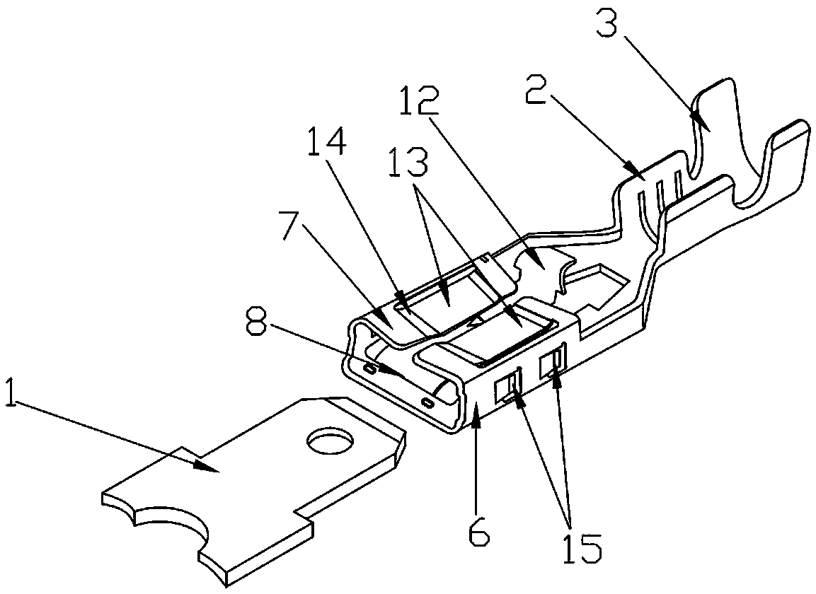
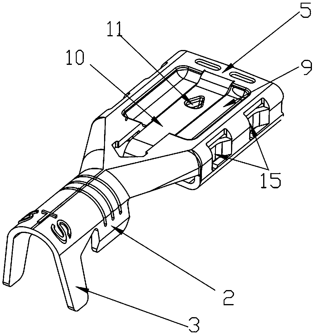
[0027] refer to Figure 1 to Figure 5 , the high-current anti-swing spring terminal specifically implemented includes a riveting foot and a spring. The riveting foot is located at the tail end of the spring terminal and is used to connect with a wire. The riveting foot is composed of a riveting core foot 2 and a riveting leather foot 3 Composition, the riveting thread leather foot 3 is arranged on the rear end of the riveting thread mandrel foot 2, and the inner surface of the riveting thread mandrel foot 2 and the riveting thread leather foot 3 are all provided with a wire placement groove 4 for matching and accommodating the wire, and the riveting thread mandrel foot 2 The inner side is provided with a raised horizontal crimping line for pressing the wire core. When connecting the wire, the wire is placed on the wire placement groove 4, and then the riveting wire core foot 2 and the riveting wire leather foot 3 are riveted to make the riveting wire core Pin 2 presses the wir...

Embodiment 2

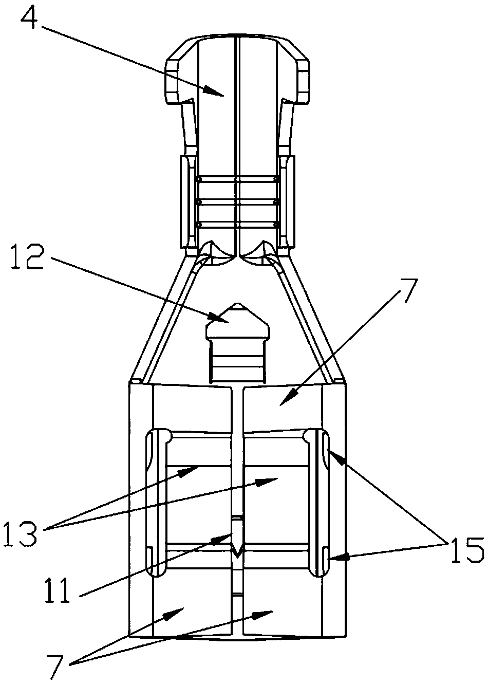
[0033] refer to Figure 6 The difference between the present embodiment and the first embodiment lies in the structure of the riveting core foot 2 and the riveting leather foot 3. Both the riveting core foot 2 and the riveting leather foot 3 extend upward and bend inward, forming a palm structure in combination. The center line of the wire placement groove 4 is perpendicular to the center line of the female end interface 8, thus forming a horizontal spring structure.

[0034] figure 1 and Figure 6 The male plug piece 1 is in the uninserted state. When the male plug piece 1 is inserted into the spring from the female end interface 8, the upper top platform 9 bears upward against the bottom surface of the male plug piece 1, and at the same time, the rear end of the upper spring piece 13 is affected by the male plug. The extrusion of the insert piece 1 withstands the rear stretching surface upwards, so that the top surface of the male insert piece 1 bears the pressure of the u...


PUM


Abstract

The invention provides a high-current anti-swing plug spring terminal relating to the field of electronic connection accessories. A plug spring for being connected with a male tab in pair is arranged at the front end of the plug spring terminal, wherein the plug spring comprises a bottom spring sheet; the left side and the right side of the bottom spring sheet are bent upwards and extend to form two side spring sheets respectively; the two side spring sheets are oppositely bent inwards separately to form two top spring sheets respectively; lower press grooves are formed in the middle parts of the two top spring sheets through stretching and stamping; the bottom surfaces of the lower press grooves are cut to form upper spring sheets; two side press grooves which are the same in structure and are arranged front to back are formed in the surfaces of the two side spring sheets through stamping; the bottom surfaces of the side press grooves are cut to form side spring sheets; when the male tab is inserted into the spring from a female end interface, the male tab can be pressed from the top surface, the bottom surface, the left surface and the right surface, so that the contact of the male tab and the spring is closer; the condition that the male tab is in firmer contact with the spring after being inserted is ensured; the stability after connection is better; the potential safety hazards of sparking and the like due to poor contact can be avoided; and the safety performance of use is strengthened.

Description

technical field [0001] The invention relates to the field of electronic connection accessories, in particular to a plug spring terminal, in particular to a large current anti-swing plug spring terminal. Background technique [0002] Spring terminals are mainly used in electrical products such as electrical connectors and distribution cabinets. The products are widely used in lighting appliances, household appliances, connectors, automobile and motorcycle accessories, connectors, wiring harnesses, lamp holders, ballasts, lighting, lamps, Electronic instruments and other products. [0003] The structure of the plug spring terminal circulating on the market is mainly composed of a plug spring for inserting a male plug and a riveting foot for riveting the wire. After the male plug is inserted into the spring, it makes electrical contact. Since the plug spring is a cavity structure, the male plug will swing left and right when inserted into the cavity of the plug spring, which i...

Claims


Application Information

Patent Timeline
Patent Type & Authority Patents(China)
IPC IPC(8): H01R13/11
CPCH01R13/113
Inventor 陈吉星李增波
Owner DONGGUAN SHANG TONG METAL ELECTRONICS
Why Eureka
Try Eureka