Hot plug method, hot plug control device, a voltage balancing method and device
A technology of voltage balance and hot-swapping, which is applied in the direction of hot-swapping power/load, circuit device, charge equalization circuit, etc. It can solve problems such as low safety and stability, contradiction between battery unit replacement and normal operation of power supply system, etc. To achieve the effect of ensuring security and stability, solving low security and stability, and ensuring security
- Summary
- Abstract
- Description
- Claims
- Application Information
AI Technical Summary
Problems solved by technology
Method used
Image
Examples
Embodiment 1
[0068] An embodiment of the present invention provides a hot swap method, the method comprising:
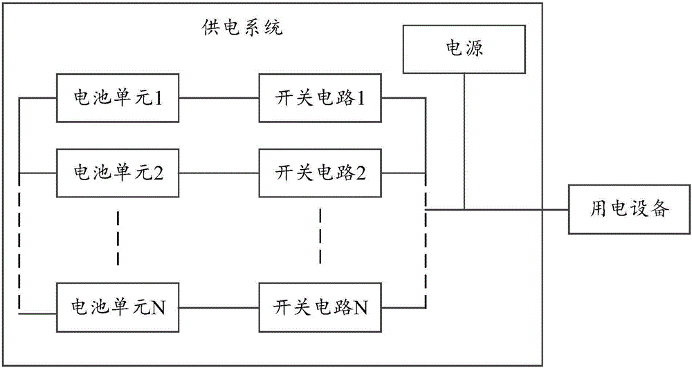
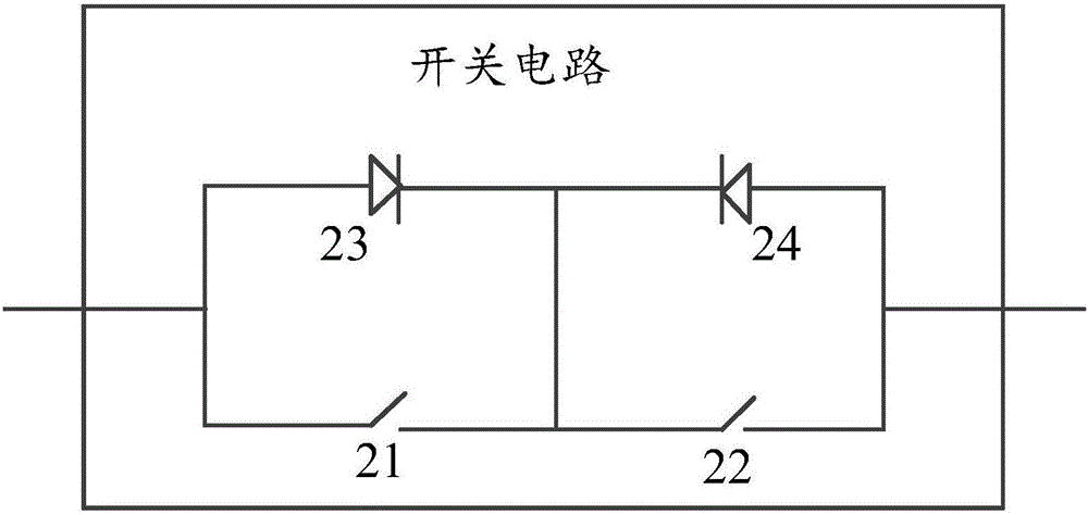
[0069] When there is a battery unit to be replaced among the multiple battery units connected in parallel, the branch where the battery unit to be replaced is cut off.
[0070] Specifically, the battery unit involved in the embodiments of the present invention may include but not limited to: battery cells, battery packs, or electric cabinets, etc., which are not particularly limited in the embodiments of the present invention. Specifically, the battery pack may include but not limited to multiple battery cells, and the battery cabinet may include but not limited to multiple battery packs and a host. In a specific implementation process, if a battery cabinet is used as a battery unit, multiple battery cabinets are connected in parallel, and the host in one of the battery cabinets can serve as the host of the entire power supply system.
[0071] It should be noted that, in the emb...
Embodiment 2
[0093] In order to solve the problem of low security and stability of the power supply system existing in the prior art, an embodiment of the present invention further provides a voltage balancing method. The method includes:
[0094] After the replacement of the first battery unit with the second battery unit among the plurality of parallel-connected battery units is completed, the charging or discharging of each battery unit is controlled according to the operating status of each battery unit.
[0095] Specifically, in the embodiment of the present invention, the operating state of each battery unit may include: a discharging state, a charging state and a resting state. Specifically, when the operating state of each battery unit is in the charging state, the power supply equipment supplies power to each battery unit; when the operating state of each battery unit is in the discharging state, each battery unit supplies power to the electrical equipment; the operating state of ...
Embodiment 3
[0140] Based on the hot swap method provided by the first embodiment above, the embodiment of the present invention further provides an embodiment of a device for realizing each step and method in the above method embodiment.
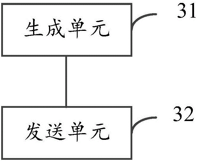
[0141] Specifically, the embodiment of the present invention provides a hot swap control device, please refer to image 3 , which is a functional block diagram of the hot swap control device provided by the embodiment of the present invention. like image 3 As shown, the device includes:
[0142] A generating unit 31, configured to generate a cutoff signal when there is a battery unit to be replaced among the plurality of parallel battery units;
[0143] The sending unit 32 is configured to send a cutoff signal to the branch where the battery unit to be replaced is located, so as to cut off the branch where the battery unit to be replaced is located.
[0144] Specifically, in the embodiment of the present invention, the branch where each battery cell...
PUM
 Abstract
Description
Claims
Application Information
 - R&D
- Intellectual Property
- Life Sciences
- Materials
- Tech Scout
- Unparalleled Data Quality
- Higher Quality Content
- 60% Fewer Hallucinations
Browse by: Latest US Patents, China's latest patents, Technical Efficacy Thesaurus, Application Domain, Technology Topic, Popular Technical Reports.
© 2025 PatSnap. All rights reserved.Legal|Privacy policy|Modern Slavery Act Transparency Statement|Sitemap|About US| Contact US: help@patsnap.com


