Supercharge Your Innovation With Domain-Expert AI Agents!

A power factor correction circuit, switching power supply and display

A power factor correction and circuit technology, applied in the field of electric power, can solve problems such as difficulty in realizing wide range input, low circuit efficiency, small voltage input range, etc., and achieve high conversion efficiency, wide voltage input range, and voltage range input Effect

Active Publication Date: 2019-06-11
TCL CHINA STAR OPTOELECTRONICS TECH CO LTD
View PDF5 Cites 0 Cited by
  • Summary
  • Abstract
  • Description
  • Claims
  • Application Information

AI Technical Summary

Problems solved by technology

[0002] Most of the PFC (Power Factor Correction) circuits currently used in TV monitors use Boost circuits or transformers for isolation and boosting. However, in traditional Boost circuits, when the output voltage is greater than 10 times the input voltage, the circuit The efficiency is very low and the output and input cannot be isolated, so the voltage input range is relatively small; when using the commonly used topology for transformer boosting, it is difficult to achieve a wide range of input

Method used


Image

  • A power factor correction circuit, switching power supply and display
  • A power factor correction circuit, switching power supply and display
  • A power factor correction circuit, switching power supply and display

Examples


Embodiment Construction

[0022] In order to enable those skilled in the art to better understand the technical solution of the present invention, the technical solution of the present invention will be further described in detail below in conjunction with the drawings and specific embodiments.

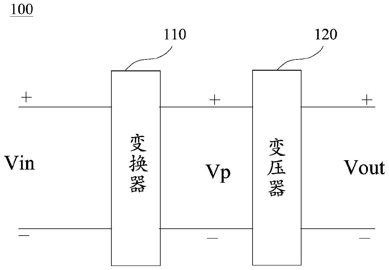
[0023] Such as figure 1 Shown is a schematic structural diagram of a power factor correction circuit embodiment of the present invention, the power factor correction circuit (hereinafter referred to as PFC circuit) 100 includes a converter 110 and a transformer 120, the input end of the transformer 120 is connected to the output end of the converter 110 , the input end of the converter 110 is used as the input end of the PFC circuit 100, and the output end of the transformer 120 is used as the output end of the PFC circuit 100, wherein:

[0024] The transformer 110 converts the input voltage Vin input to the converter 110 into a set voltage Vp, and outputs it to the transformer 120 . The transformer transform...


PUM


Abstract

The invention discloses a power factor correction circuit. The power factor correction circuit comprises a converter and a transformer, wherein the input end of the converter is used as the input end of the power factor correction circuit; the input end of the transformer is connected with the output end of the converter, and the output end of the transformer is used as the output end of the power factor correction circuit; the converter is used for converting input voltage to pre-set voltage and outputting the voltage to the transformer; and the transformer is used for transforming the pre-set voltage to obtain output voltage. The invention further discloses a switching power supply applying the power factor correction circuit and a display device. According to the power factor correction circuit disclosed by the invention, the converter is used for converting the input voltage to the pre-set voltage and the transformer is used for transforming the pre-set voltage, so that a wide voltage input range is realized and is wider than a voltage input range of an existing PFC circuit; and the conversion efficiency is high.

Description

technical field [0001] The invention relates to the technical field of electric power, in particular to a power factor correction circuit, a switching power supply and a display. Background technique [0002] Most of the PFC (Power Factor Correction) circuits currently used in TV monitors use Boost circuits or transformers for isolated boosting. However, in traditional Boost circuits, when the output voltage is greater than 10 times the input voltage, the circuit The efficiency is very low and the output and input cannot be isolated, so the voltage input range is relatively small; when the commonly used topology is used for transformer boosting, it is difficult to achieve a wide range of input. Contents of the invention [0003] The object of the present invention is to provide a power factor correction circuit, a switching power supply and a display to realize the input of a wide voltage range, aiming at the above-mentioned shortcomings of the existing power factor correc...

Claims


Application Information

Patent Timeline
Patent Type & Authority Patents(China)
IPC IPC(8): H02M1/42
CPCH02M1/42Y02B70/10
Inventor 李文东
Owner TCL CHINA STAR OPTOELECTRONICS TECH CO LTD
Features
  • R&D
  • Intellectual Property
  • Life Sciences
  • Materials
  • Tech Scout
  • Unparalleled Data Quality
  • Higher Quality Content
  • 60% Fewer Hallucinations
Learn More